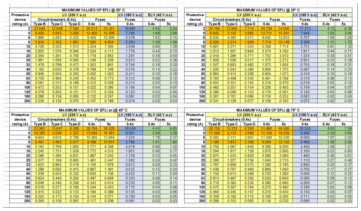
5Maximum values of EFLI (Zs) at 230 V a.c. and 42 V a.c. for selected temperatures#
Table 5 shows EFLI values for protective devices for selected temperatures (20, 25, 45 and 75 degrees C). The tables are obtained from the recorded AS/NZS 3000 values at 75°C as follows:
First, the EFLI values for temperature 20°C are obtained as follows:
Where:
R₂₀ is impedance at 20°C, in ohms R₇₅ is impedance at 75°C, in ohms
α = 0.00393, is the temperature coefficient of resistivity of copper at 20°C, in °C-1
Having obtained the values for EFLI at 20°C, the EFLI for any other temperature ϴ (> 20°C) is obtained as follows:
𝑅𝑅𝜃𝜃= 𝑅𝑅20[1 + 𝛼𝛼(𝜃𝜃−20)]
The Extra Low Voltage (ELV) EFLI values for the 2A and 5A fuses commonly used in traffic signal controllers (see Section 5.1) were obtained from controlled testing under laboratory conditions applying a voltage of 39V so that at the rated ELV of 42V these values are conservative. Other ELV EFLI values for protective devices rated 6A onwards were extrapolated from existing EFLI values at 230V.
Table 5 - Maximum EFLI values for selected protective devices and temperatures
5.1Maximum EFLI values for fast-acting 2A, 5A and 8A fuses used in TSC#
In new traffic signal controllers (TSC), the lamp switching circuit for each signal group aspect is protected by a slow-acting 2A or fast-acting 5A fuse cartridge readily replaceable from the front of the logic module. Older TSCs might have fast-acting fuse rated 8A.
The most commonly used fuses are Bussman® and Littelfuse®.
Slow-Acting fuse
- LITTEL 215 series (5 mm x 20 mm)
- BUSSMAN S505 series (5 mm x 20 mm)
Fast-Acting fuse
- LITTEL 216 series (5 mm x 20 mm)
- BUSSMAN S501 series (5 mm x 20 mm)
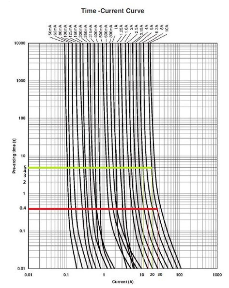
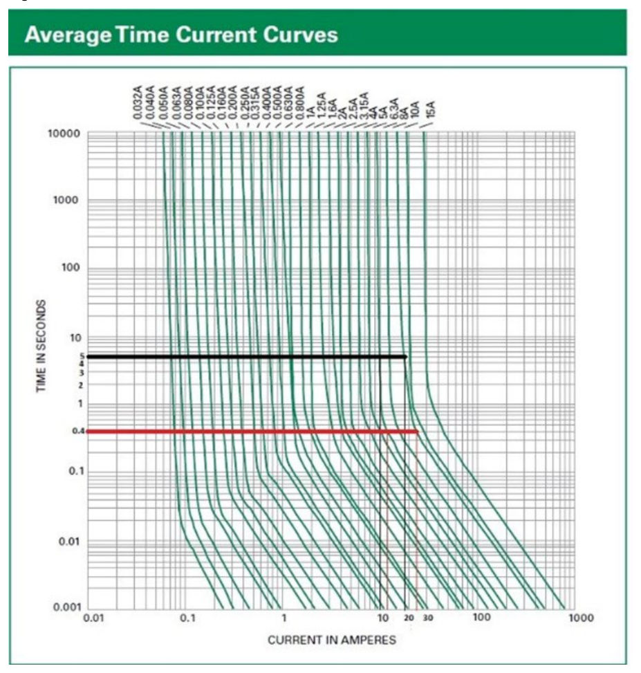
The EFLI values shown in Table 5 are based on values obtained from the fuse datasheets, testing, and recording the worst case.
The Time-current curves for Bussman® and Littelfuse® showing the disconnection currents at 0.4s and 5s are shown in Figure 5.1a and Figure 5.1b respectively.
For ELV circuits as per Table 5, 5s disconnection time is appropriate. 0.4s disconnection time has also been included for reference or if required in specific aquatic / marine settings.