
Multi-message sign arrangements#
In the Queensland MUTCD, the REDUCE SPEED multi-message panel (TC1220 or TC1712) may only be used to supplement a speed restriction (or speed limit AHEAD) panel where a speed zone reduction is implemented or on the initial speed restriction sign on approach to the site where this sign is used as a repeater speed restriction sign for traffic approaching / entering the site.
In this scenario, the Designer chose to use the REDUCE SPEED panel (1200 x 300), with a 600 x 600 WORKER (symbolic) and the 60 km/h speed restriction sign. The 60 km/h speed restriction panel is placed closest to traffic (Queensland MUTCD Part 3 Clause 4.4.2(c)).
- For requirements and information regarding the use of multi-message signs, refer to Queensland MUTCD Part 3 Clauses 4.2.2, 4.4.4 and 4.5.2, and Appendices A and B.
- For requirements on the use of the REDUCE SPEED message in Queensland, refer to Queensland MUTCD Part 3, Appendix A and Table A.2.
- For information regarding the WORKER (symbolic) sign, refer to Queensland MUTCD Part 3 Clause 4.6.5.
- 10.Space in the additional warning areas may be required in order to provide room for a traffic control vehicle without it obstructing the safety buffer. In this scenario, a Category 2 road with a speed limit above 80 km/h, a lane closure and night works, the Designer should consider using a TMA in the additional warning area. In this scenario, the Designer has determined a TMA is warranted.
QGTTM Section 5.8.1 requires a clear distance of at least 40 m in front of the TMA as a roll ahead distance and Figure 5.10 allows the safety buffer for the work area if required to also be used for the TMA roll ahead distance.
The TMA roll ahead distance of 40 m in front of the TMA must be kept clear of any workers, materials, equipment, or obstructions (see Note 11).
The Designer has chosen not to also use the work area safety buffer for the TMA roll ahead distance, meaning the additional warning area needs to be long enough to accommodate the TMA and the roll ahead distance of 40 m for the TMA. Allowing 15 m for the length of the deployed TMA and vehicle, plus the 40 m roll ahead, gives a minimum additional warning area of 55 m.
As a further consideration, as it is undesirable to be asking drivers to do more than one action at a time, the Designer has chosen to also consider the distance between where traffic merges and the impact of the traffic control station location (vehicles stopping in the queue) and include additional space in the additional warning area so that the estimated traffic queue of 184 m is located wholly within the single lane section. This should reduce the risk of side swipes and rear end crashes (due to merging and stopping for the end of queue at the same time / location) and is achieved in this scenario by extending the additional warning area from 55 m to 250 m (184 m queue + 6 from the start of queue to the TC station + 45 m to the 40 km/h sign + 15 m to the safety buffer).
- For considerations when treating additional warning areas, refer to QGTTM Part 3, Section 5.8.
- For information regarding the use of TMAs, refer to QGTTM Part 3, Section 5.8.1.
- For information regarding the design and operation of arrow boards, refer to Queensland MUTCD Part 3 Clause 4.14.2.
- 11.Confirm there are no devices in the roll ahead distance for the TMA. The TMA is located at the start of the additional warning area and allowing for the TMA unit in the deployed position, the vehicle and 40 m roll ahead distance gives a length of 55 m from the end of the taper where no other traffic control devices (excluding delineation) should be located. The additional PTS sign is the closest traffic control device to this area and is located 70 m from the end of the taper and, thus, 15 m clear of the area required for the TMA, including the roll ahead distance.
- 12.A merge taper is required to reduce the two lanes of traffic into a single lane past the work area. The transition area is located immediately prior to the additional warning area. Drivers generally find a merge to the right is easier and, as such, a merge from the left-hand lane into the right-hand lane is the preferred merge arrangement. In this scenario, from Table 5.6 and based on a traffic speed in this area of 60 km/h, the merge taper length will be 60 m. This assumes (at this point in time) that the speed restriction sign to reduce traffic speeds to 60 km/h prior to the primary PTS sign will be located 200 m or more (Figure 2.2) prior to the start of the merge taper (see Note 17 for confirmation).
- For recommended lengths of merge tapers, refer to QGTTM Part 3, Table 5.6, and Figure 2.2.
- For information regarding the design of merge tapers, refer to QGTTM Part 3, Section 5.9.1.
- 13.Lane status signs are required to give advance warning of the merge taper ahead. These signs are located in advance of the transition area (in the advance warning area) and, in the QGTTM, are to be positioned one sign spacing (Table 2.2) in advance of the start of the taper. The QGTTM also includes an option where the permanent speed limit of the road is 80 km/h or greater (which is the case in this scenario) that the distance between the lane status sign and the merge taper may be increased to two sign spacings. The location of the lane status sign may be affected by other signs (such as the traffic control signs) and may need to be adjusted to accommodate minimum sign spacing requirements of other signs and devices which are located in advance of the start of the taper (see Note 15).
- For recommendations on required lane status signage, refer to QGTTM Part 3, Section 2.5.3, Figure 5.24, and Table 2 2.
In this scenario, the Designer originally chose to use the MERGE RIGHT panel (1200 x 300), with a 600 x 600 LANE STATUS (symbolic) and the MERGE IN TURN panel (to encourage courteous merging). The lane status panel is placed closest to traffic.
The MERGE IN TURN panel, if not used, may be replaced with a yellow blank panel (or another appropriate panel such as the WORKER (symbolic) panel). A WORKER (symbolic) panel will be required on approach to the work area and is currently provided with the speed limit reduction to 60 km/h sign assembly.
- For requirements and information regarding the use of multi-message signs, refer to Queensland MUTCD Part 3 Clauses 4.2.2, 4.4.4 and 4.5.2, and Appendices A and B.
- For information regarding the MERGE IN TURN sign in Queensland, refer to the Queensland MUTCD Part 3, Appendix A and Table A.2.
- For information regarding the WORKER (symbolic) sign, refer to Queensland MUTCD Part 3 Clause 4.6.5.
- 14.Locate the primary PTS sign one sign spacing (Table 2.2) in advance of the start of the merge taper, as the primary PTS sign (or any sign other than delineation) should not be located within the taper area. The primary PTS sign also needs to be a minimum of 90 m (see Note 8) from the end of queue location (which is also the start of the additional warning area in this scenario). Assuming the primary PTS sign is located more than 200 m beyond the 60 km/h speed restriction sign (see Note 18 for confirmation), this would place the primary PTS sign at 105 m (60 m for the merge taper and 45 m for the minimum sign spacing from the merge taper) from This is greater than the minimum of 90 m (Table 2.3) from the end of queue.
In this scenario, 105 m is used in lieu of the 90 m sight distance to the end of queue (this is an acceptable adjustment from the requirements discussed in Note 8).
- For sign spacing requirements, refer to QGTTM Part 3, Table 2.2, and Figure 2.2.
- For sight distance requirements (end of queue), refer to QGTTM Part 3, Table 2.3.
- For maximum distance between PTS signs, refer to QGTTM Part 3, Table 4.4a and Figures 4.4 and 4.5.
Consider the relationship between several of the signs and devices in the transition and advance warning areas including the primary PTS, lane status, 60 km/h speed limit signs, and the merge taper. The layout and order of these elements of the design could be done a few different ways, and this is just one way that the Designer in this scenario has adopted (see the sign layout for this example TGS in Figure 4.1 for the arrangements and order of elements used in this area).
The primary PTS sign is located one sign spacing (Table 2.2) in advance of the start of the merge taper (see Note 14).
Locate the lane status sign one sign spacing (Table 2.2) in advance of the primary PTS sign. This then locates the lane status sign two sign spacings from the start of the merge taper, which is not an issue and is an option where the permanent speed limit of the road is 80 km/h or greater as discussed in Note 13.
Assuming the 60 km/h speed reduction will be 200 m or less from the lane status sign (a 100 km/h speed value will be used for the spacing of signs in this zone – see Note 19 for confirmation). The spacing from the lane status sign to the primary PTS sign will be 100 m and, therefore, the distance from the lane status sign to the start of the taper will be 145 m (100 m between lane status and primary PTS + 45 m from primary PTS to the start of taper). Two sign spacings are used but, due to the location of the speed zone reduction to 60 km/h, different speed values are used and the sign spacing distances are different.
The 60 km/h speed restriction sign may then be located a further sign spacing in advance of the lane status sign. Again, using a 100 km/h speed limit in this area (see Note 19 for confirmation), the 60 km/h speed restriction sign will be located 100 m in advance of the lane status sign.
- For sign spacing requirements, refer to QGTTM Part 3, Table 2.2, and Figure 2.2.
The extent of the 60 km/h zone is now known.
The total length of the 60 km/h speed zone is 540 m (100 m to lane status sign + 100 m to primary PTS sign + 295 m to TC station + 45 m to 40 km/h sign) and is greater than the minimum length of a 60 km/h zone of 150 m (Table 5.5).
Also from Table 5.5, the length of the 60 km/h zone on approach to the TC station of 495 m (540 m total length of 60 km/h zone – 45 m to TC station) is greater than the 150 m minimum required on approach to the TC station.
There is a requirement to provide speed limit repeater signs at a maximum spacing of 500 m and the length of the 60 km/h speed zone at 540 m requires a repeater speed limit sign to be used (see Note 20 for adjustment to lane status sign arrangement in Note 13).
- For information on speed zones, recommended speed zone lengths, repeater speed sign spacings and methods for reducing speeds, refer to QGTTM Part 3, Section 5.5, and Tables 5 5 and 5.6.
Confirm the merge taper distance, as the location of the 60 km/h speed restriction sign is now known. Note 12 assumed the 60 km/h speed restriction sign would be 200 m or more from the start of the taper and the merge taper distance would be 60 m.
The 60 km/h speed restriction sign is located 245 m from the start of the taper, so the assumption in Note 12 and the merge taper distance of 60 m is correct.
Confirm the sign spacing for the primary PTS sign, as the location of the 60 km/h speed restriction sign is now known. Note 14 assumes the 60 km/h speed restriction sign would be 200 m or more from the primary PTS signs and a speed of 60 km/h could be used for the spacing between the primary PTS and the start of the merge taper.
The 60 km/h speed restriction sign is located 200 m from the primary PTS sign, so the assumption in Note 14 and the distance between the primary PTS sign and the start of the merge taper of 45 m is correct.
Confirm the sign spacings for the 60 km/h speed restriction sign, the lane status sign, and the primary PTS sign, as the location of the 60 km/h speed restriction sign is now known.
Note 15 assumes the 60 km/h speed restriction sign would be 200 m or less from the lane status sign and a speed of 100 km/h could be used for the spacings between the 60 km/h speed restriction sign, the lane status sign, and the primary PTS sign.
The 60 km/h speed restriction sign is located 100 m from the lane status sign and the primary PTS sign is a further 100 m from the lane status sign, so the assumption in Note 15 and the distance between the 60 km/h speed restriction sign, the lane status sign and the primary PTS sign of 100 m are both correct.
Thus, determining speed limits and their extents (locations) including how they reduce or increase through a site is a critical part of the design exercise which affects many other elements / decisions.
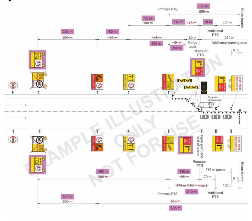
20. Note 16 determined the requirement for a repeater speed restriction sign.
Adding an additional speed restriction sign into the layout would require significant adjustment of sign spacings and other requirements. The only alternative to finding space for and adding an extra sign into the layout would be to incorporate the 60 km/h speed restriction sign into an existing multi-message sign assembly. The lane status multi-message sign (see Note 13) is the only choice as all other multi-message signs within the 60 km/h speed zone do not have an option for including the 600 x 600, 60 km/h speed restriction panel.
This breaks the 540 m total length of the 60 km/h speed zone into a 100 m segment and a 440 m segment which meets the 500 m maximum spacing requirement for repeater speed restriction signs.
In this scenario, the Designer originally chose (Note 13) to use the MERGE RIGHT panel (1200 x 300), with a 600 x 600 LANE STATUS (symbolic) and the MERGE IN TURN panel (to encourage courteous merging). The lane status panel is placed closest to traffic. This multi-message sign arrangement now requires adjustment to accommodate a repeater speed restriction sign.
The Designer has chosen to replace the MERGE IN TURN panel with a 600 x 600 speed restriction sign. The lane status panel now moves to the location of the MERGE IN TURN panel as the speed restriction panel must be placed closest to traffic.
The reason for a temporary speed restriction sign should be clear to the road user. In this case, the 60 km/h speed zone is for the presence of traffic control; however, due to the special requirements for the PTS signs, a speed limit cannot be used with the traffic controller (or PTCD) symbol. In this scenario, the Designer has used the lane status panel with the repeater speed restriction sign to reinforce the reduced traffic speeds prior to the merge point.
The Designer in this scenario has chosen to use the 1200 x 300 MERGE RIGHT panel on both sides of the road. It would also be acceptable to use the DO NOT OVERTAKE or MERGE IN TURN (1200 x 300) panel in lieu of the MERGE RIGHT message on the sign on the right hand side of the road. Vehicles in the right hand lane do not need to merge right, as this lane continues, but they may need to allow merging vehicles space to enter this lane.
- For requirements and information regarding the use of multi-message signs, refer to Queensland MUTCD PART 3 Clauses 4.2.2, 4.4.4 and 4.5.2, and Appendices A and B.
- For information on speed zones, recommended speed zone lengths, repeater speed sign spacings and methods for reducing speeds, refer to QGTTM Part 3 Section 5.5 and Tables 5.5 and 5.6.
21. A speed buffer comprising either an advance warning (speed limit AHEAD sign) or incremental reductions in speed limit (speed restriction sign/s of intermediate value) is required in advance of the 60 km/h speed zone for the TC station.
In this scenario, the Designer has chosen to use a 60 km/h speed limit AHEAD sign which is located (as per QGTTM) a distance double the speed limit (using the higher speed zone value – not the new reduced speed limit) in advance of the 60 km/h speed restriction sign. As the
If the speed zone in advance of the 60 km/h zone is 100 km/h, '100' is doubled and the 60 km/h speed limit AHEAD sign is located 200 m in advance of the 60 km/h speed restriction sign for the reduced 60 km/h speed zone.
In the interim, while waiting for the national documents to be amended, the QGTTM Part 3 Section 5.5 provides the requirements for speed signs and methods for reducing speeds to be used in Queensland.
- For information on speed zones, recommended speed zone lengths, repeated speed sign spacings and methods for reducing speeds, refer to QGTTM Part 3 Section 5.5 and Tables 5.5 and 5.6.
- For information and considerations regarding the signing of speed zones, refer to Queensland MUTCD Part 3 Clauses 3.4.4 and 4.7.6.
- For requirements and information regarding the use of multi-message signs, refer to Queensland MUTCD Part 3 Clauses 4.2.2, 4.4.4 and 4.5.2 and Appendices A and B.
In this scenario, the Designer chose to use the new AS 1742.3 version of the speed limit AHEAD panel (600 x 900), with a 600 x 600 ROAD WORK AHEAD message (see Note 22). The remaining 300 x 600 panel is filled with a yellow blank. The speed limit AHEAD panel is placed closest to traffic.
For requirements and information regarding the use of multi-message signs, refer to Queensland MUTCD Part 3 Clauses 4.2.2, 4.4.4 and 4.5.2, and Appendices A and B.
- 22.As this is only a short-term site, advance warning signs, such as a ROADWORK AHEAD sign, would not be required by Queensland MUTCD Part 3 (which adopts the AS 1742.3 requirement for all long-term sites). It is, however, an option where additional advance warning is required.
In this scenario, the Designer has determined that additional advance warning is required, due to the high-speed approach (also see requirements in Note 23).
As a ROADWORK AHEAD sign is being used, and this is a short-term site, the use of a ROADWORK 1 km AHEAD sign is not warranted.
In this scenario (see Note 21), the ROADWORK AHEAD sign is located with the speed limit AHEAD sign.
As works are occurring at night, a pair of flashing lamps are to be used with the ROADWORK AHEAD multi-message sign assembly.
- For information and considerations regarding ROADWORK AHEAD signs, refer to QGTTM Part 3, Sections 4.8 and 5.11 and Queensland MUTCD Part 3 Clause 4.6.2.
- For information and considerations regarding night works, refer to QGTTM Part 3, Section 6.7.
- 23.QGTTM (Section 4.8) requires the use of a ROADWORK AHEAD sign or a VMS in advance of a Traffic Control station in all situations.
The ROADWORK AHEAD sign (or a VMS) is required to be at a distance as per Table 4.4b in advance of the primary PTS sign (Section 4.8 Item 6).
In this scenario, the ROADWORK AHEAD sign is to be at least four times the speed limit of 100 km/h (4 x 100), namely 400 m in advance of the primary PTS sign, which it is exactly.
For the distance from the primary PTS sign to ROADWORK AHEAD sign or VMS, refer to QGTTM Part 3, Section 4.8(6), and Table 4.4b.
- 24.Termination signs are used to alert road users to the end of a work zone and a resumption of normal traffic conditions.
The termination signs typically include both a speed reinstatement sign and the END ROADWORK sign.
The DRIVE SAFELY multi-message panel is not included in AS 1742.3 but is permitted as an optional sign in the Queensland MUTCD, where the DRIVE SAFELY multi-message panel may only be used with the END ROADWORK panel. In this scenario, the DRIVE SAFELY message is included with the termination sign.
The END ROADWORK panel is required at all static sites (QGTTM Part 3 Section 5.12) and is also required due to the ROADWORK AHEAD sign being used in this scenario (Queensland MUTCD Part 3 Clause 4.6.2).
NEXT X km sign is used. This will be resolved in a future national revision of one or both of AS 1742.3 and AGTTM.
Given both relevant clauses in AS 1742.3 (Clause 4.6.2) and AGTTM Part 3 (Section 5.12) regarding the use of the END ROADWORK sign are 'accepted' in the Queensland MUTCD Part 3 and the QGTTM Part 3 respectively, and both require the use of the sign, the Designer has included the END ROADWORK panel in this scenario.
The END ROADWORK sign would also be an appropriate panel to use with a speed restriction panel for all sites which require a speed zone reinstatement to be applied on leaving the site.
- For information and considerations regarding termination signs, refer to QGTTM Part 3, Section 5.12.
- For requirements on the use of the END ROADWORK sign, refer to Queensland MUTCD Part 3 Clause 4.6.2.
- For requirements on the use of the DRIVE SAFELY message in Queensland, refer to Queensland MUTCD Part 3, Appendix A and Table A.2.
In the Queensland MUTCD, the DRIVE SAFELY multi-message panel is permitted; however, it may only be used with the END ROADWORK panel.
In this scenario, the Designer chose to use the DRIVE SAFELY panel (1200 x 300), with a 600 x 600 END ROADWORK panel and the 100 km/h speed limit reinstatement sign. The 100 km/h speed restriction panel is placed closest to traffic (Queensland MUTCD Part 3 Clause 4.4.2(c)).
For requirements and information regarding the use of multi-message signs, refer to Queensland MUTCD Part 3 Clauses 4.2.2, 4.4.4 and 4.5.2, and Appendices A and B.
- 25.Determine the spacing of termination signs from the work area.
In this scenario, the end of the work area is 145 m (within 200 m) from the speed reduction to 40 km/h and there is no opposing traffic, so there are no offset speed zones to consider; thus, 60 km/h is to be used as the traffic speed in this area when using Table 5.8, which gives 45 m as the termination area distance in this scenario. As the speed limit increases from 40 km/h to 100 km/h, the Designer has considered 45 m is too short and vehicles would likely be travelling much faster than 40 km/h toward the end of the work area as they could see the termination signs ahead and start speeding up early (while still in the work area).
QGTTM Section 5.12 introduces the concept of placing the termination signs an 'appropriate distance' from the work area. This is much more critical for sites with no opposing traffic flows as offset speed zones are not a factor. Some considerations could include:
- a)using sight distance to the termination sign as the spacing for the termination signs – from Table 2.3 and a speed limit of 60 km/h, this would give a termination distance of 90 m, or
- b)assume that, like a reduction in speed (as per Section 2.5.3 and Figure 2.2), an increase in speed limit may also use an area of 200 m in advance of the speed limit increase where the new speed limit will apply to sign spacings. As the new speed limit is 100 km/h, this would equate to a sign spacing (Table 2.2) of 100 m as the termination distance.
As 45 m was considered too short and is a relatively small distance in this road environment, the Designer in this scenario has adopted 100 m as the termination distance. This distance is not considered too long in this road environment (high-speed, multi-lane divided road).
- For necessary termination distances, refer to QGTTM Part 3, Section 5.12, and Table 5.8.
- For sign spacing, refer to QGTTM Part 3, Section 2.5.3, Figure 2.2, and Table 2.2.
- 26.The extent of the 40 km/h speed zone is now known. The total length of the 40 km/h speed zone is 245 m (45 m to the work area + 100 m work area + 100 m termination area) and is less than the maximum length of a 40 km/h speed zone of 500 m for workers within 1.2 m of traffic and greater than the minimum length of 100 m.
As the length of the 40 km/h speed zone is less than 500 m (the maximum requirement for a repeater sign), there is no requirement to repeat the 40 km/h speed restriction sign within this zone.
For information on speed zones, recommended speed zone lengths, repeater speed sign spacings and methods for reducing speeds, refer to QGTTM Part 3 Section 5.5 and Tables 5 5 and 5.6.
- 27.Traffic cone / bollard spacing requirements are provided in Table 5.3, which are recommended maximums and may be reduced to ensure adequate delineation is provided dependant on site conditions.
In this scenario, traffic cones or bollards have a recommended maximum spacing of:
- a) in the merge taper, 12 m (use spacing for 60 km/h, as it is not a traffic control taper)
- b) for the lane closure, between the merge taper and the 40 km/h speed restriction sign, 12 m (in a 60 km/h speed zone), and
- c) for the lane closure within the 40 km/h speed zone, 4 m (in a 40 km/h speed zone).
The Designer has chosen to adopt these recommended maximum traffic cone / bollard spacings and has provided on the TGS the minimum number of traffic cones / bollards required at this maximum spacing.
For traffic cone / bollard requirements and spacing, refer to QGTTM Part 3, Section 5.4, and Table 5.3.
- 28.Although not a Category 3 road, in this scenario (a Category 2 road), the Designer has chosen to use traffic cones that are the large size (900 mm high). This is in accordance with Queensland MUTCD Part 3 Clause 4.11.1 (which adopts the cone sizes as per AS 1742.3), as this worksite is located on a high-speed (100 km/h), high-volume road (divided multi-lane) with works occurring at night.
For traffic cone size requirements, refer to QGTTM Part 3, Section 5.4.1, and Queensland MUTCD Part 3 Clause 4.11.1.
- 29.Extend the traffic cones or bollards delineating the closed lane beyond the end of the work area by a short distance to allow work vehicles exiting the work area continued separation from the traffic lanes. The delineation of the closed lane may be extended a minimum of the termination distance from Table 5.8 or 45 m past the work area (as this location is within 200 m of the reduction in speed zone, 60 km/h is to be used as the traffic speed in this area when using Table 5.8).
In this scenario, the END ROADWORK sign is 100 m from the end of the work area (see Note 25). The closed lane delineation could be extended all the way to the END ROADWORK signs; however, the Designer in this scenario chose to extend the delineation 45 m past the end of the work area which should be enough to allow work vehicles exiting the work area separation from the traffic lanes. These traffic cones should also assist with road user speed limit compliance when approaching the end of the work area.
For necessary termination distances, refer to QGTTM Part 3, Section 5.12, and Table 5.8.
- 30.As this is a short-term site, the Designer has chosen to use the T5-7 hazard marker (the narrow vertical hazard marker in lieu of the longer T5-4 version) to assist with delineation of the merge taper. Three of the T5-7 hazard markers are to be used, with one placed at the start and end of the taper, and one in the middle.
Although the works are conducted at night, the use of these hazard markers along with the traffic cones forming the merge taper and assisted by the arrow board on the TMA (located at the end of the merge taper) will provide sufficient visibility of the merge taper location for approaching drivers. The T5-7 hazard markers are to be located 1 m behind the merge taper formed by the traffic cones. Also, as the traffic cones are 900 mm high, the three hazard boards should be located between the traffic cones when viewed on approach (not behind or very close to the high traffic cones as this would impact the visibility of the hazard markers).
For information and considerations regarding hazard markers, refer to QGTTM Part 3 Section 5.4.2 and Queensland MUTCD Part 3 Clause 4.11.3.
To further assist with delineation on approach to the taper and to close off the shoulder in this area, QGTTM allows, as an option, the use of four traffic cones at 4 m centres placed on the approach to the taper. In this scenario, the Designer has chosen to use the four traffic cones on the approach to the start of the taper and these will be located on the edge line. A T5-7 hazard marker (the narrow vertical hazard marker in lieu of a T5-5 version) will be placed adjacent to the first of these traffic cones to close off the 1 m sealed shoulder.
The Design has chosen the T5-7 hazard marker due to the short-term nature of the works and the ease of installation of this hazard marker (as compared to a T5-5 or T5-4 hazard marker).
For information on the cones in advance of a taper, refer to QGTTM Part 3, Section 5.9.1.
As this is a multi-lane road, it is recommended to duplicate signs on both sides of the carriageway. In this scenario, the Designer has chosen to duplicate the signs as there is enough space on the shoulders to accommodate this without affecting other road users such as people walking or riding bikes.
People walking or riding bikes were fully considered as part of the TMP process, and the Designer determined that, in this scenario (being a high-speed, multi-lane divided road with works occurring at night), there are no people walking and only very experienced people riding bikes (due to the 100 km/h speed limit), who would likely take the lane in the single-lane section on approach to the TC station (60 km/h speed zone) and past the work area (40 km/h speed zone). It was noted in the TMP that people riding bikes may be assisted by the traffic controller (if required) holding traffic while the people riding bikes traverse the work and termination areas.
The Designer has also made the decision to duplicate the signs in the single-lane section of the worksite, due to both the general road environment and the use of 900 mm-high traffic cones in this area which may affect visibility of the multi-message signs located in the closed lane. This choice only added two extra multi-message signs (as the speed limit signs are required to be duplicated).
- For recommendations on duplicating signs on multi-lane roads, refer to QGTTM Part 3, Section 2.5.3.
- For information on duplicating speed signs, refer to QGTTM Part 3, Section 5.5.
When stopping traffic, it is possible for queues to extend beyond the predicted end of queue (and back towards the primary PTS sign), generating an increased risk of end-of-queue collisions.
Contingency planning (for what to do on site) if this happens is an important consideration when preparing the TGS design. The traffic controller is to monitor queue lengths to ensure the end of queue is not extending back beyond the predicted end of queue location which, in this scenario, is the end of the taper. If this was to happen, the following would need to occur:
- a)another traffic controller or traffic management implementer would need to add additional PTS signs further in advance of the TC station, so the minimum sight distance requirements in Table 2.3 from this new location of the primary PTS sign to the end of the queue is achieved
- b)the speed reduction signs (to 60 km/h) must be not less than one sign spacing from this new location of the primary PTS sign, and
- c)if speed reduction signs are relocated, the advance speed limit warning or incremental speed limit reduction signs may also require relocation.
- d)The location of other signs such as the ROADWORK AHEAD sign will need to be adjusted due to the new primary PTS sign location.
If the end of queue is getting close to (but not beyond) the end of queue location, this would be a trigger for the TC to keep a close watch on the end of queue location and to take action such as warning the other TTM team members that implementing the contingency plan may be required so they can be prepared for this requirement (should it be necessary).
- For information regarding end-of-queue safety provisions, refer to QGTTM Part 3, Section 4.8.
- For information regarding monitoring the end-of-queue location, refer to QGTTM Part 7 Section 2.9.2 for the Traffic Controller and QGTTM Part 6 Sections 3.3.3, 7.7 and 7.8 for the Traffic Management Implementer.
- For additional information regarding end-of-queue safety provisions in Queensland, refer to the Guideline – Traffic Management at Works on Roads, Chapter 1, Section 2.
Depending on the width of the shoulder at the TC station, the 'open' lane may require delineation on the right-hand side on approach to the TC station where vehicles may drive (or may even be observed driving) around the end of the boom barrier using the sealed / unsealed shoulder.
If required, provide a three traffic cone taper across the shoulder (as a short taper to close the shoulder) and a minimum of four traffic cones (at 4 m spacing) on the right-hand side of the 'open' lane to define the traffic lane on approach to the TC station. In this scenario, the Designer has determined that, due to a sealed shoulder of only 1 m and an unsealed shoulder This could be included by the Designer as a contingency plan that could be implemented if this was observed on site to be an issue.
The boom for the boom barrier could also be extended out to its maximum length to also cover part of this shoulder area to discourage drivers from using the shoulder area to drive around the boom.
For additional information regarding the use of supplementary devices at roadworks to reduce speed in Queensland, refer to the Guideline – Traffic Management at Works on Roads Chapter 1 Section 1.
Ensuring adequate sight distance to each traffic control device is also a design requirement. In this scenario, a relatively short site on a straight, multi-lane divided road, sight distance would not be expected to be an issue. In other environments and roadside conditions, it may be a significant issue that would require device locations to be adjusted appropriately.
For information regarding sight distance requirements, refer to QGTTM Part 3, Section 2.5.4, and Table 2.3.
As works are occurring at night, all signs should have a traffic cone (900 mm high – see Note 28) placed at the base of each sign on the traffic side of the multi-message frame. In this scenario, while some street lighting is available, it is well-spaced, and the Designer has determined that this traffic cone is required for all signs.
The Designer has also determined that additional lighting is required for both the TC station (see Note 6), the taper / lane closure and the work area.
For information and considerations regarding night works (activity during low light), refer to QGTTM Part 3, Section 6.7 and Part 6, Section 9.
As workers are within 1.2 m of traffic and the 40 km/h speed zone past the work area is a primary risk mitigation strategy to reduce risk / injury to workers, it is essential that actual traffic speeds are monitored for compliance with the 40 km/h speed zone and that action is taken if traffic speeds are above 40 km/h.
Monitoring traffic speeds on approach to the TC station (within the 60 km/h speed zone) is also required.
Speed monitoring would be a role for the lead TMI onsite and would be assisted by feedback from the TC in terms of approach speeds to the traffic control station and feedback from workers regarding traffic speeds past the works area. Drive-throughs with traffic are also a good way to check on traffic speeds and driver behaviour through the site (and assists to identify areas for improvement).
- For information regarding monitoring traffic speed for compliance, refer to QGTTM Part 3, Sections 2.5.9 and 5.5.
- For additional information regarding the use of supplementary devices at roadworks to reduce speed in Queensland, refer to the Guideline – Traffic Management at Works on Roads, Chapter 1, Section 1.
- For information regarding the use of temporary speed humps and rumble strips, refer QGTTM Part 3, Sections 5.5.2 and 5.5.3.
Installation and removal order numbers and any special instructions could be added to the TGS design. For the purpose of this example, the installation and removal order numbers are not included on Figure 4.1 and the process for implementation and removal is provided following.