6Traffic signals and road lighting#
6.1Electrical components#
Refer to the department’s SD1699 Traffic signals/Road lighting/ITS – Parts list, which provides details of standard electrical equipment items.
6.2Equipment configuration#
Details follow of equipment configurations for traffic signals and road lighting equipment.
6.2.1Traffic signals#
Transport and Main Roads traffic signals consist of a number of major components as shown in Figure 6.2.1 in this manual. Note the supply is typically unmetered. Currently, there are three types of field terminals, which are: upper-mounting assembly terminal (for traffic signal post), traffic signal terminal panel (for joint-use pole) and traffic signal junction box (for mast arm). Testing on Traffic Signal Controllers (TSC) shall be as per manufacturer’s requirements.
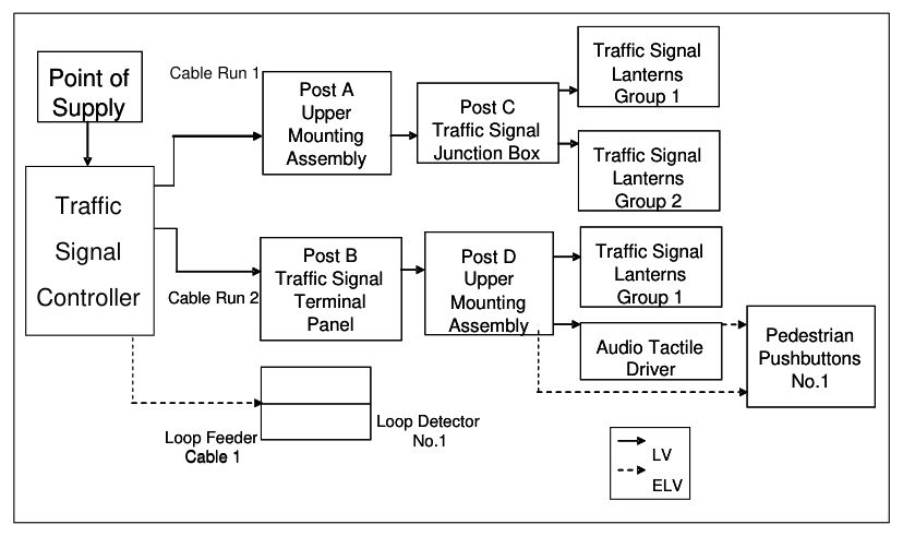
Traffic Signal Lanterns Group 1 · Traffic Signal Lanterns Group 1 · Point of Supply · Point of Supply · Cable Run 1 · Post A · Post A · Post C · Post C · Traffic Signal · Traffic Signal · Upper Mounting Assembly · Upper Mounting Assembly · Junction Box · Junction Box · Traffic Signal · Traffic Signal · Post B · Post B · Post D · Post D · Upper Mounting Assembly · Upper Mounting Assembly · Controller · Cable Run 2 · Cable Run 2 · Terminal Panel · Terminal Panel · Loop Detector · Loop Detector · Loop Feeder · Loop Feeder · No.1 · No.1 · Cable 1 · Cable 1 · Traffic Signal Lanterns Group 2 · Traffic Signal Lanterns Group 2 · Traffic Signal Lanterns Group 1 · Traffic Signal Lanterns Group 1 · Pedestrian Pushbuttons · Pedestrian Pushbuttons · Audio Tactile Driver · Audio Tactile Driver · No.1 · No.1 · LV · LV · ELV · ELV
6.2.2Road lights (park, pathway and pedestrian tunnels)#
Transport and Main Roads is responsible for the maintenance of Rate 3 road lighting (public lighting installed on roadways and public thoroughfare). Note the supply is normally unmetered. Where three phase circuits (CCTS) are used, the luminaire load must be balanced across the phases as evenly as possible. The electrical connection for luminaires must be such that, in a three phase connected system, luminaires on adjacent poles should not be on the same phase. Typically, a road light switchboard has three outgoing light CCTS, but this can be extended to be a total of five outgoing CCTS (in certain approved cases). For this typical configuration, each outgoing lighting circuit consists of three phases (A, B and C) and it is intended that road lights are connected so that every third pole is connected to the same phase. This, ideally, results in each phase having approximately one third of the total electrical load. Refer to Figure 6.2.2 in this manual for a road light configuration example. Note that cable sizes shown are typical only and cable connection from road light to neutral is not shown. A single photocell mounted on a pole adjacent to the pillar or on a post-mounted switchboard is used to operate simultaneously all the contactors controlling outgoing lighting CCTS.
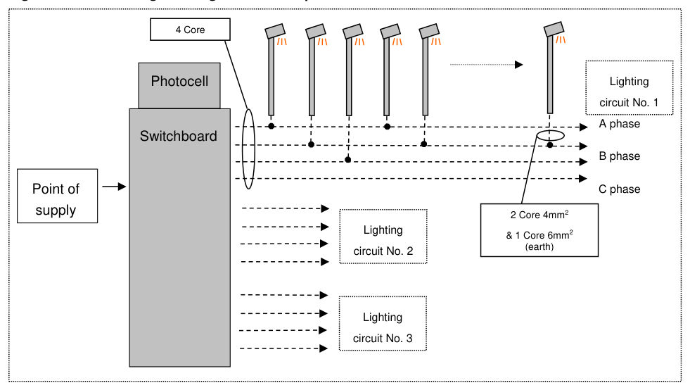
4 Core · Photocell Lighting circuit No. 1 · A phase · Switchboard · B phase · Point of supply · C phase · 2 Core 4mm2 & 1 Core 6mm2 (earth) · Lighting circuit No. 2 · Lighting circuit No. 3