
8Electrical tests#
This section defines the testing requirements for periodic verification of traffic signals and road lights equipment installations. Tests shall be completed as per Appendices A – C and results shall be recorded.
| Test | Equipment | Purpose | |
|---|---|---|---|
| 1 | Visual inspection | — | Visual inspection is to be completed to ensure that there are no local hazards prior to completing remainder of the tests. |
| 2 | Earth continuity | Ohmmeter (multimeter) | Earth continuity tests is to be completed to ensure that earthing system has been installed in an appropriate manner. |
| 3 | Neutral integrity | Voltmeter (multimeter) | Test for integrity of the neutral is to ensure that touch voltages are minimised. |
| 4 | Earth resistance | Ohmmeter (multimeter) | The resistance from any point of the electrical installation required to be earthed, to the point where the main earthing conductor (MEC) is connected to the neutral conductor (MEN connection) of the supply system, shall be low enough to permit the passage of current necessary to operate the circuit protective devices. Note that resistance of the MEC is to be less than 0.5 Ω. |
| 5 | Insulation resistance | Insulation resistance tester (if energised use current clamp) | Insulation resistance tests are necessary to ensure that the insulation resistance between all live conductors and earth, or all live parts and earth is adequate to ensure the integrity of the insulation. |
| 6 | Polarity | Ohmmeter (multimeter) | Polarity tests are carried out to ensure the correct connection of active, neutral and earth conductors to electrical equipment. |
| 7 | Correct circuit connections | — | Tests are necessary to ensure that protective earthing conductors do not normally carry current, and/or no short circuit exists due to risk of fire damage or personal injury. |
| 8 | Earth Fault Loop Impedance | Loop tester | An Earth Fault Loop Impedance (EFLI) test is to confirm the fault loop impedance value of each circuit between active conductor and a protective earthing conductor will be low enough to ensure the operation of the protective device during a fault. |
| 9 | Verification of RCD | RCD tester | Testing of an RCD is carried out to ensure that the RCD operates and disconnects the designated circuit as required. |
| 10 | Infrared thermal imaging | Thermal imager | Thermal images can indicate hot spots which can be caused by, for example, loose connections or faulty equipment. |
Touch voltage can be carried out where risk assessment dictates, usually when an item of electrical equipment is suspected of causing an electric shock.
8.1Test equipment (typical)#
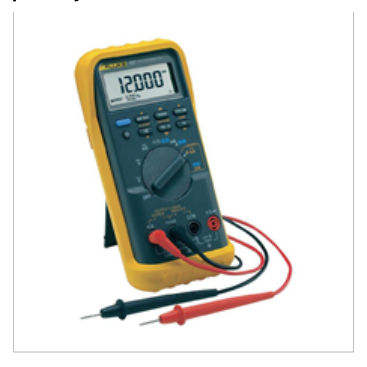
A dual impedance digital multimeter is recommended to confirm if any inducted voltages are present in high impedance CCTS that are de energised. Source: Fluke
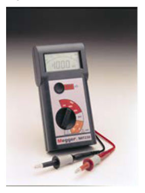
Source: Megger
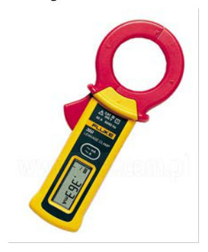
Source: Fluke
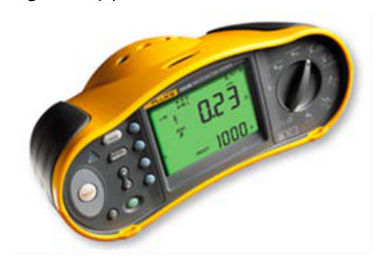
Earth Fault Loop Impedance and Fault Loop Impedance tests must be able to draw at least 4 Amps of current during test. Source: Fluke
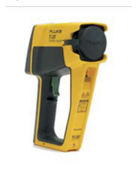
Source: Fluke
8.2Test requirements#
8.2.1Visual#
A visual inspection shall be carried out prior to testing to confirm there are no immediate hazards and that the electrical installation is of suitable condition to proceed.
8.2.2Earth continuity#
The purpose of the test is to ensure that all exposed metal is maintained at earth potential, and to permit the circuit protection to operate under fault conditions.
8.2.3Neutral integrity#
A neutral integrity test is to confirm that touch voltages are minimised. Possible causes are loose or poor neutral connections. Balanced phase to phase voltages and phase to neutral voltages which are significantly out of balance indicate that the neutral may be floating due to a poor or open circuit neutral connection; for example, A ph – 265 volts, B ph – 240 volts, C ph – 215 volts (3 phase circuit).
8.2.4Main earth conductor resistance#
An earth resistance test will confirm whether the connection of the equipment to earth is no greater than 0.5 Ω.
8.2.5Insulation resistance#
An insulation resistance test requires the supply to be disconnected. The integrity of the insulation is stressed by applying a direct current at 500 V (excluding exemptions, refer to Wiring Rules Clause 8.3.6.1). As per AS 3019 Clause 4.7.4, leakage current testing is accepted (as an alternative to insulation resistance test in limited testing) when it is desirable to minimise effects on the installation and avoid the need to disconnect the supply. This test requires measurement of the current in the active and neutral conductors. Note the accepted limit of leakage current permitted is to be less than or equal to 10 mA.
8.2.6Polarity#
A polarity test is conducted to ensure the active and neutral wires are connected to the correct terminals.
8.2.7Correct circuit connections#
This test is to ensure that there are no short circuit between conductors, transposition of conductors that could result in the earthing system and any exposed conductive parts of the electrical installation becoming live, or interconnection of conductors between different CCTS.
8.2.8Earth Fault Loop Impedance#
Earth Fault Loop Impedance to be conducted on C.Mains, and final CCTS of:
- switchboards (SWBS)
- poles (lighting and signals)
- cabinets and controllers
- mastarms
- ITS cabinets
- ITS poles.
Refer to Table 8.2.8 for maximum values of Earth Fault Loop Impedance (Zs) at 230 Vac and 20°C.
| Protective device rating A | Circuit breakers Type B 75°C | Circuit breakers Type B 20°C | Circuit breakers Type C 75°C | Circuit breakers Type C 20°C | Circuit breakers Type D 75°C | Circuit breakers Type D 20°C | Fuses 75°C | Fuses 20°C | Fuses 75°C | Fuses 20°C |
|---|---|---|---|---|---|---|---|---|---|---|
| 6 | 9.583 | 7.880 | 5.111 | 4.203 | 3.067 | 2.522 | 11.500 | 9.456 | 15.330 | 12.605 |
| 10 | 5.750 | 4.728 | 3.067 | 2.522 | 1.840 | 1.513 | 6.390 | 5.254 | 9.200 | 7.565 |
| 16 | 3.594 | 2.955 | 1.917 | 1.576 | 1.150 | 0.946 | 3.070 | 2.524 | 5.000 | 4.111 |
| 20 | 2.875 | 2.364 | 1.533 | 1.261 | 0.920 | 0.756 | 2.090 | 1.719 | 3.590 | 2.952 |
| 25 | 2.300 | 1.891 | 1.227 | 1.009 | 0.736 | 0.605 | 1.640 | 1.349 | 2.710 | 2.228 |
| 32 | 1.797 | 1.478 | 0.958 | 0.788 | 0.575 | 0.473 | 1.280 | 1.053 | 2.190 | 1.801 |
| 40 | 1.438 | 1.182 | 0.767 | 0.630 | 0.460 | 0.378 | 0.960 | 0.789 | 1.640 | 1.349 |
| 50 | 1.150 | 0.946 | 0.613 | 0.504 | 0.368 | 0.303 | 0.720 | 0.592 | 1.280 | 1.053 |
| 63 | 0.913 | 0.750 | 0.487 | 0.400 | 0.292 | 0.240 | 0.550 | 0.452 | 0.940 | 0.773 |
| 80 | 0.719 | 0.591 | 0.383 | 0.315 | 0.230 | 0.189 | 0.380 | 0.312 | 0.680 | 0.559 |
| 100 | 0.575 | 0.473 | 0.307 | 0.252 | 0.184 | 0.151 | 0.270 | 0.222 | 0.480 | 0.395 |
| Protective device rating A | Circuit breakers Type B 75°C | Circuit breakers Type B 20°C | Circuit breakers Type C 75°C | Circuit breakers Type C 20°C | Circuit breakers Type D 75°C | Circuit breakers Type D 20°C | Fuses 75°C | Fuses 20°C | Fuses 75°C | Fuses 20°C |
|---|---|---|---|---|---|---|---|---|---|---|
| 125 | 0.460 | 0.378 | 0.245 | 0.202 | 0.147 | 0.121 | 0.210 | 0.173 | 0.430 | 0.354 |
| 160 | 0.359 | 0.296 | 0.192 | 0.158 | 0.115 | 0.095 | 0.160 | 0.132 | 0.300 | 0.247 |
| 200 | 0.288 | 0.236 | 0.153 | 0.126 | 0.092 | 0.076 | 0.130 | 0.107 | 0.230 | 0.189 |
Where some installations may not be able to meet this standard due to the high ambient temperature, a Registered Professional Engineer Queensland (RPEQ) Electrical shall determine suitable alternative EFLI value, taking into account the specific site geometry.
Prior to any works, refer to site specific design data to confirm equipment type/rating installed.
8.2.9Verification of Residual Current Device#
A number of traffic controllers are equipped with a Residual Current Device (RCD) protected socket outlet, which is designed for ancillary electrical equipment.
A visual inspection is required to make sure these RCD protected socket outlets are not subject to any operation of traffic signals. A tripping time test of the integrated RCD is required, using an RCD tester in accordance with AS/NZS 3017 Clause 3.7.2.2, to confirm tripping time does not exceed 300 ms. The use of the integral test button is not acceptable.
8.2.10Infrared thermal imaging#
As per AS/NZS 3019 Clause 5.8, the integrity of switchboard connections should be tested out with a thermal imaging device. Both the ambient temperature and maximum temperature measured should be recorded and any items whose temperature is significantly above the ambient noted.
The possible faults which can be indicated through use of infrared thermal imaging include:
- high impedance connection
- overloads
- imbalanced CCTS
- faulty equipment
- damaged switches
- faulty fuses.
8.2.11Touch voltage testing#
This is to ensure that the installation is fit for purpose in the environment in which it is installed and does not contribute to a dangerous electrical incident.