
15Installation requirements#
15.1Pre-installation#
The Contractor shall allow the Administrator access to inspect all equipment prior to installation. Witness Point 1 The Contractor shall replace all damaged equipment and/or materials.
15.2Equipment#
Equipment and associated systems shall:
- be designed and installed to provide quick, easy and safe access for maintenance purposes, and
- minimise, and wherever practicable eliminate, the need for traffic control during maintenance activities.
Where the equipment and/or associated system has components located on opposite sides of the carriageway, any physical connection shall be immune to any future road widening envisaged in the Contract. The crossroad connections shall be made in conduits either in the sub grade of the road or under the road.
15.3Wiring enclosures#
Each ITS device Site shall be provided with conduit infrastructure (including pits and ducts) necessary for the complete operation of the device. Conduit infrastructure includes cable access from the backbone conduit network to the ITS field Enclosure / Cabinet and/or field device. Cable infrastructure shall be installed in accordance with MRTS91 Conduits and Pits. After installation of cables, the associated conduits and/or glands shall be sealed to prevent vermin entry.
15.4Equipment enclosures#
Ground mounted equipment enclosures shall be installed on a concrete plinth. The gap between the plinth and enclosure shall be vermin-proof and prevent corrosion of the enclosure or its fixings. Enclosures shall be installed such that when all doors are fixed in the open position, visibility of the approaching traffic flow is maximised for maintenance personnel working in and around the enclosure. For flood-prone locations, the equipment enclosure shall be installed above the identified flood risk level (e.g., Q20, Q50, Q100). The specific mounting height above the flood risk level shall be designed in accordance with relevant standards and guidelines.
15.5Clearance height#
Unless otherwise specified, where an ITS device is mounted above the carriageway, the vertical clearance from the bottom of the support structure and/or the device enclosure to the road surface shall be a minimum 6.1 m.
For tunnels, the ITS structure, including all support elements and device enclosures, shall be installed completely outside the kinematic zone or carriageway to ensure safe passage of vehicles and compliance with relevant standards.
15.6Site selection#
The general layout, positions, reduced level for the footing, speed zones for the ITS device and details of the barriers shall be shown on the Contractor's design documentation. The Contractor's proposed ITS device locations shall be verified by Site inspection. Hold Point 4 The final ITS device location, size and mounting type, and location and positioning of related protection barriers shall be shown on the design documentation. The final design documentation shall be submitted to the Administrator in accordance with the requirements of the Contract. Mounting structures shall be in accordance with MRTS61 Gantries and Support Structures for Road Signs, Tolling Systems and ITS Devices. Where devices are installed over trafficable areas such as a carriageway or bicycle / pedestrian pathway, the device shall be fitted with a secondary fixing system that will minimise the risk of the device failing and resulting in a hazardous situation.
15.7Vehicle barriers#
Where vehicle barriers associated with the ITS device are to be provided, these shall be installed prior to commencing civil Works for the device's mounting foundations. Hold Point 5
15.8Site maintenance access#
Where practicable, vehicular or non-vehicular access points shall be provided for maintenance access. The practicability of providing such access points shall be determined through a risk analysis and feasibility study conducted by the contractor and approved by the Principal. These assessments shall consider site-specific factors such as:
- Safety risks to maintenance personnel and road users
- Physical constraints of the site (e.g., terrain, structures, or environmental conditions)
- Cost implications and constructability
- Traffic flow and operational impacts, and
- Compliance with relevant standards and guidelines.
15.8.1Vehicular access#
Where deemed practicable, permanent vehicle access points shall be provided within 50 m of each ITS equipment Site to allow maintenance vehicles to enter and exit the equipment Site from the carriageway safely. Vehicular access points and associated vehicle setup areas described in this clause need not be provided along structures such as a bridge, tunnel or an overpass. Access points shall:
- be arranged to prevent all vehicles from entering the Site in the usual approach direction of carriageway traffic
- be secured to prevent unauthorised vehicular access provide a minimum sight-distance of upstream carriageway equal to the safe-stopping distance of the carriageway's design speed
- allow maintenance vehicles to enter and exit the Site without protruding into trafficable carriageway lanes
- be arranged in a manner which avoids the need for traffic control during maintenance Works, and
- wherever practicable be co-located with help phone bays.
Where road-side barrier treatments exist or are required adjacent to the equipment Site, these shall be in accordance with Queensland MUTCD Part 3 and AS/NZS 3845.
Where the access point adjoins a carriageway with design speed >60 km/h, the access point shall allow the vehicle to pass through the access point parallel to the direction of carriageway traffic flow.
A suitable set-up area for the maintenance vehicle shall be provided close enough to the equipment for safe operation of maintenance activities and allow the vehicle to be parked within 10 m of the equipment.
The vehicle entrance / exit point, access track and set-up area shall be suitable for all-weather access for a maintenance vehicle pertinent to the maintenance activity.
15.8.1.1Fibre Optic Joint Access#
Access points for fibre optic joints shall be designed to facilitate maintenance activities by allowing a maintenance vehicle to park directly adjacent to the fibre optic joint. This is to enable the fibre optic joint to be brought into the vehicle for maintenance purposes.
Access points for fibre optic joint maintenance shall:
- Permit the fibre optic joint to be moved a minimum of 10 m from its location in the pit or enclosure into the maintenance vehicle.
- Provide sufficient space for the maintenance vehicle to park safely and securely adjacent to the fibre optic joint without obstructing trafficable carriageway lanes.
- Be arranged to avoid the need for traffic control during maintenance works, and
- Ensure all-weather access for the maintenance vehicle, including the entrance / exit point, access track, and set-up area.
Wherever practicable, these access points should be co-located with other vehicular access points described in Clause 15.8.1 to optimise maintenance efficiency and minimise disruption.
15.8.2Non-vehicular access#
Where it is not practicable to provide a vehicular access and set-up point, the following requirements apply for non-vehicular access to ITS equipment Sites.
Permanent personnel access points from the carriageway to the equipment Site shall be provided within 10 m of each item of ITS equipment. Access points shall:
- be arranged to prevent vehicles from entering the Site, and
- minimise the need for traffic control during maintenance Works.
Where road-side barrier treatments exist or are required adjacent to the equipment Site, these shall be in accordance with Queensland MUTCD Part 3 and AS/NZS 3845.
A parking area suitable for maintenance vehicles shall be provided on the shoulder / verge adjacent to the access point.
The parking area shall:
- allow personnel to alight safely from both sides of the vehicle concurrently and access the Site without entering trafficable carriageway lanes
- be located to minimise the unprotected exposure of maintenance personnel to traffic flows; and
- provide a minimum sight-distance of upstream carriageway (from within the vehicle) equal to the distance required to allow the vehicle to accelerate to 80% of the carriageway's design speed.
Where road-side barrier treatments exist or are required adjacent the equipment Site, these shall be designed in accordance with Queensland MUTCD Part 3 and AS/NZS 3845.
15.9Maintenance area for equipment Sites#
An access path shall be provided to each ITS equipment Site for the safe movement of maintenance personnel between a parked maintenance vehicle and the equipment. The access path and the area around the equipment Site shall be:
- evenly graded so as not to exceed 1:3 gradient. If this cannot be achieved, stairs shall be provided to AS 1657
- suitable for safe, all-weather access
- lit to category P4 of AS/NZS 1158
- resistant to damage from environmental effects such as erosion
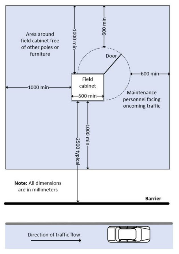
- provided with a clearance area of minimum 600 mm width around open doors
- provided with a clearance area of minimum 1000 mm width around closed enclosures / cabinets, and
- arranged to provide sufficient space for inspection, maintenance, repair and rescue.
A visual representation of this clearance area is shown in Figure 15.9.
When determining clearance areas, distance shall be considered to physical objects, unsafe terrain and restricted zones. While maintenance activities are taking place on LV connected equipment, an exclusion zone is to be maintained that adheres to the requirements of the Queensland Electrical Safety Regulation 2025.
Concrete steps may be provided to optimise path alignment. Where steps and/or handrails are provided, these shall be in accordance with the relevant standards and codes.
A concrete slab shall be provided with dimensions given in SD1423 and SD1679.
The access path and the area around the equipment Site shall allow easy maintenance to remain free of trip hazards.