
7Mechanical and physical requirements#
The mechanical and physical requirements defined in MRTS201 General Equipment Requirements, MRTS61 Gantries and Support Structures for Road Signs, Tolling Systems and ITS Devices and/or TRUM Manual, Volume 3, Part 5: Design Guide for Roadside Signs apply to work provided under this Technical Specification. Additional mechanical and physical requirements for eTCS equipment provided under this Technical Specification are described below.
7.1Design life#
Unless otherwise specified, the design life of the eTCS components shall be as follows:
- structures: a minimum of 40 years
- enclosures: a minimum of 20 years
- LEDs / pixels: a minimum of five years, and
- electronics: a minimum of 10 years.
7.2Mounting structure#
7.2.1General mounting requirements#
The eTCS shall be supported by fixed or portable mounting structures designed in accordance with MRTS61 Gantries and Support Structures for Road Signs, Tolling Systems and ITS Devices, AS 1170.1 and AS 1170.2 when installed with all supporting hardware and accessories used to operate the signs including the solar panels, where fitted.
7.2.2Fix-mount eTCS#
For fix-mount eTCS, the location and type of mounting structure to be provided to mount each eTCS shall be designed for the site conditions in which they are intended to be used and shown on the design documentation. The mounting structure shall comply with the requirements of MRTS201 General Equipment Requirements and MRTS61 Gantries and Support Structures for Road Signs, Tolling Systems and ITS Devices and/or TRUM Manual, Volume 3, Part 5: Design Guide for Roadside Signs when installed with all supporting hardware and accessories used to operate the signs including the solar panels, where fitted. If the sign forms an integral part of a Traffic Signal installation, then the sign, mounting hardware, and cabling shall be suitable for mounting on a standard Transport and Main Roads traffic signal pedestal.
7.2.3Portable eTCS#
Portable eTCS shall be capable of being mounted on a:
- vehicle
- a trailer, or
- a concrete block support structure.
in a location consistent with Part 10 of the Queensland Guide to Traffic Management (QGTM). The mounting structures supporting the eTCS shall be designed for the site conditions in which they are intended to be used.
7.2.3.1Vehicle mounted eTCS#
The vehicle on which the eTCS is mounted shall conform to the requirements of the host vehicle specified in the Queensland MUTCD Part 3 and this Technical Specification. If required, vehicle mounted eTCS shall be fitted with solar panels.
7.2.3.2Trailer mounts#
Where the eTCS is mounted on a trailer, the sign and solar panel array shall have a mechanical system which allows the sign and solar panel be safely secured to the trailer for transportation.
The mechanical system shall also allow for the sign and solar panel to be safely erected on site to ensure the sign is clearly visible to motorists and that the solar panels can be adjusted to ensure optimum solar exposure and maximum energy generation anywhere in Queensland.
The mechanical systems shall ensure that the sign cannot rotate due to wind gusts up to the ultimate wind speed the structure is designed.
The trailer shall comply with the applicable Australian Design Rules and shall be suitable for registration in accordance with the statutory requirements of the State of Queensland.
7.2.4Mounting structure design documentation#
The design documentation shall include the following:
- For fix-mount eTCS, it shall include details of the final footing design, location of the structure and the Reduced Levels (RLs) prior to fabrication of the footing and support structure, and
- For Vehicle, trailer and/or concrete block support structure, it shall include evidence of compliance with this Technical Specification and certified by a RPEQ.
In either case, the Contractor shall submit the final design documentation to the Principal's representative for acceptance. Hold Point 3
7.3Display enclosure physical requirements#
The sign enclosure shall house the sign and associated control electronics, including the eTCS controller and comply with the requirements of MRTS201 General Equipment Requirements. Where installed in a tunnel and or coastal environments, the enclosure shall be made of Marine Grade Aluminium.
7.3.1Layout and dimensions#
The layout, LED placement and dimensions of the eTCS face shall be as specified in the standard LED version of the TC sign as displayed in the departmental website or as specified in the contract. Examples of eTCS signs are shown below.
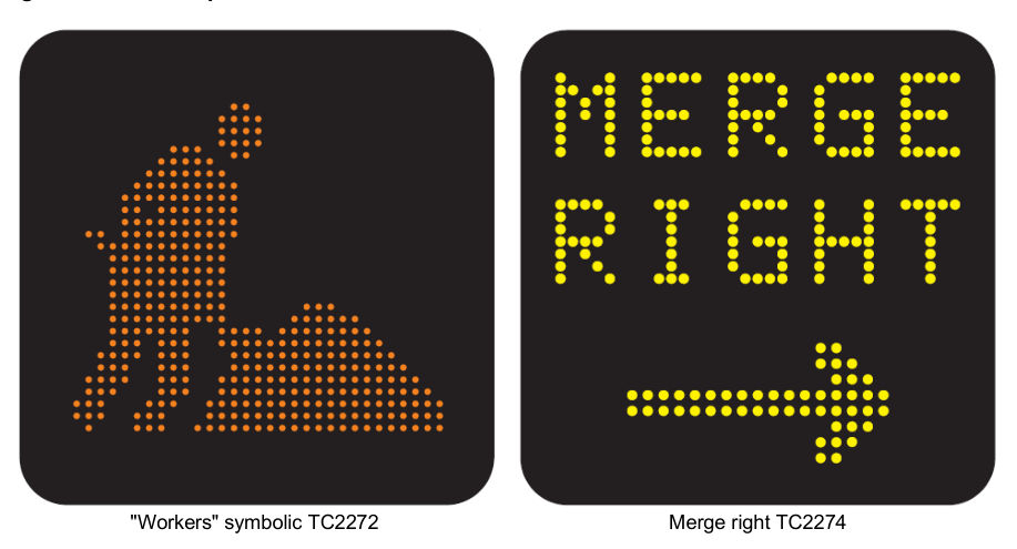
"Workers" symbolic TC2272 · Merge right TC2274
Below is the link to Transport and Main Road's TC signs. http://www.tmr.qld.gov.au/business-industry/Technical-standards-publications/TC-signs.aspx
7.3.2Exterior finish and surfaces#
A ripple finish is required to all painted surfaces on the display enclosure. Surface colours shall be:
- front face surrounding the active display, and bottom external face: matte black, or APO Grey with external matte black target board
- remainder of external surfaces: APO grey, and
- interior: matte black, or natural finish with internal black backing board.
Where an internal backing board is used, this shall allow easy removal to access the eTCS display.
7.3.3Front cover material#
A protective front cover shall be fitted to the display enclosure to form a viewing window. The front cover material shall be a single, clear Lexan® sheet, or equivalent, with a non-reflective finish. The sheeting shall be manufactured from sign-grade material SG300 with a thickness at least equal to that recommended by the manufacturer, and in all cases, at least 4.5 mm. The viewing window shall be such that when installed, the sides and bottom edges of the display face are fully visible at viewing angles of ± 45° (horizontal) and ± 30° (vertical) to the axis perpendicular to the front plane of the display.
7.3.4Front cover retention method#
The front cover shall be able to be removed from outside the eTCS for maintenance without requiring removal of internal components. Fasteners and retaining cover strips shall be easily accessible.
The front cover retention and seal design shall allow for thermal expansion properties of the front cover material. The front cover surrounding framework and cover strips shall provide the required weather proofing and strength for both positive and negative wind pressures.
7.4Field cabinets#
The eTCS interface to a Field Processor (FP) or telecommunications equipment shall be installed in a suitable roadside enclosure, being either:
- a ground mounted field cabinet complying with requirements of MRTS226 Telecommunications Field Cabinets, or
- an integral enclosure complying with the requirements of MRTS201 General Equipment Requirements installed on the eTCS mounting structure.
Unless otherwise specified by the Principal, a lockable door shall be located on the front of the sign housing. The door arrangement shall be compatible with the mounting structure members.