
8eTCS Display requirements#
8.1General#
The eTCS display technology shall be light emitting diode (LED). The display pixels may be formed by arranging one or more LEDs in a cluster to achieve the required luminance levels.
The horizontal and vertical pitch of the pixels in the matrix shall be in accordance with AS 4852.2.
The eTCS display pixels shall be in modules of a size capable of being removed and installed by hand via access door(s) or screen.
The eTCS shall only display the messages as specified in the contract, and detailed in the Queensland MUTCD, TORUM, or TC Signs.
8.2Failures#
Facilities shall be included to detect failures within the display control system. The sign shall blank the display in the event of a sign processor fault. Time to blank shall be a configurable setting.
The Display Unit (DU) shall monitor communications with the eTCS controller and blank that display if a loss of communication is experienced. The communications timeout period shall be a configurable setting.
The eTCS controller shall be able to detect LED failures even if the LEDs may be required to be 'off' at the time of the periodic check. The display shall be blanked upon failure of two per cent of contiguous pixels for each displayed image or failure of more than 20% of LEDs.
On power restoration after loss of power, the eTCS shall become available for activation and remain blank until commanded by the eTCS controller or TMS. At no time shall partial or incomplete frames be displayed.
An eTCS light sensor failure or a single LED failure (provided that the cumulative LED loss remains below the two per cent and/or 20% thresholds described above) should not result in blanking of the display.
8.3LED output#
Each individual LED shall be driven with a continuous current with no peak and/or magnitudes exceeding 70% of the LED manufacturer's maximum continuous rating. For LEDs in a 5 mm or smaller diameter package, peak magnitudes of the LED current shall not exceed 20 mA. For messages containing multiple colours, the apparent brightness of all colours in the message shall appear the same.
8.4Character and graphical display unit#
8.4.1Display unit format and placement#
The type of eTCS proposed for each location shall including their font, format and placements of LED's shall comply with the requirements defined in the relevant TC sign.
8.4.2Display unit colour#
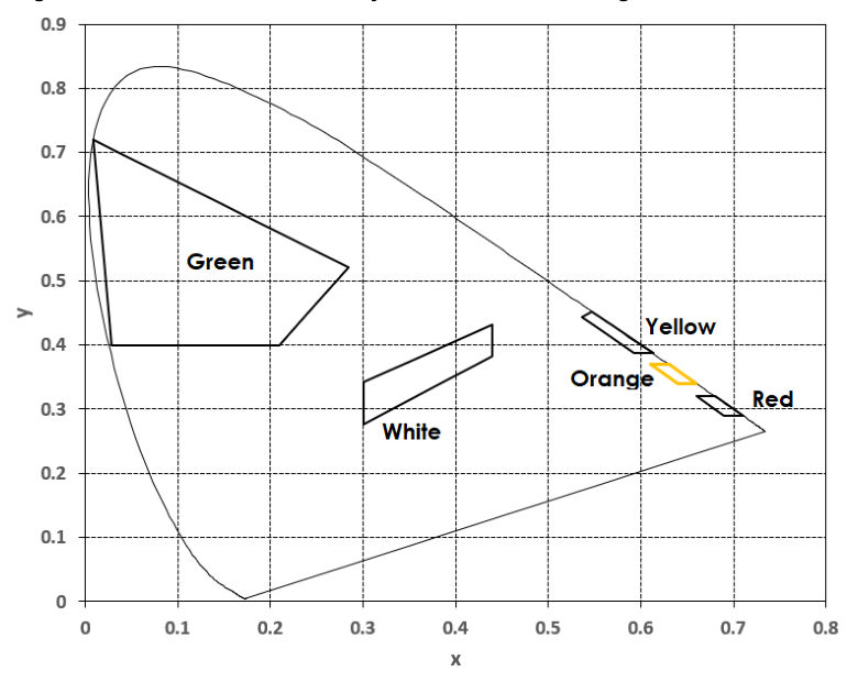
Sign faces as defined in TORUM, Queensland MUTCD, or TC Signs display messages using Red, Yellow, Green, White, black and occasionally Orange colours. Where any of these colours are required to display a specific sign face, the chromaticity coordinates of Red, Yellow, Green and White shall be as defined by their respective region coordinates in AS 4852.1, on a matt black background.
Where Orange is required to display a sign face, the chromaticity coordinates of the orange LED shall be as shown in Table 8.4.2 below and Figure 8.4.3.
| Colour | 1 | 2 | 3 | 4 | |
|---|---|---|---|---|---|
| Orange | x | 0.63 | 0.61 | 0.64 | 0.66 |
| y | 0.37 | 0.37 | 0.34 | 0.34 |
8.4.3Colour mixing#
Where each of the Red, Yellow, Green, or White colours are generated by mixing, such as through the use of RGB LEDs or other technology, the resulting colours shall remain within their corresponding chromaticity coordinates as defined in AS 4852.1 for all brightness levels.
Where the Orange colour is generated by mixing, such as through the use of RGB LEDs or other technology, the resulting colour shall remain within the chromaticity coordinates of the orange LED as shown in Table 8.4.2 (and Figure 8.4.3), for all brightness levels.
Each sign display colour generated by mixing shall remain within its corresponding specified chromaticity coordinates for at least 10 years of continuous switching and operation
8.5Display Changes#
Signs are not required to implement the TSI-SP-003 protocol application layer messages relating to the creation (setting) of text and graphics frames, since the eTCS signs' frames are inherently static.
Thus, the sign's controller shall be able to:
- display a single fixed message frame continuously when commanded
- display a single fixed message frame continuously based on time of day
- flash the annulus when commanded, and
- display any combination of all the above formats.
eTCS signs shall store message formats inside the sign controller that are set by a controlling field processor.
8.6Fallback displays#
Facilities shall be included to detect failures within the eTCS and the display control system(s). On detection of a failure, the display shall be blanked to prevent confusing displays to the motorist. Loss of communications with TMS shall also be considered an eTCS failure and shall result in the display(s)
being blanked after a pre-set time period. This time period shall be a variable, able to be set by TMS, with a range of 60 seconds to 600 seconds.
8.7Optical performance#
8.7.1Luminance#
The luminance and luminance ratio of the LED shall comply with the requirements of AS 4852.1
8.7.2LED dimming#
The LED intensity shall be controlled to provide maximum legibility distances for the complete range of ambient light under which the eTCS shall operate.
An eTCS shall have a minimum of 10 and a maximum of 100 LED brightness levels. The brightness levels shall be in units of percentage of maximum brightness.
8.7.3Luminance intensity half angle#
The luminance half angle shall be at least 15° for eTCS.
8.7.4Luminous intensity uniformity#
The requirements for Luminous Intensity uniformity shall comply with AS 4852.1.
The luminous intensity uniformity shall be maintained at all dimming levels.
8.7.5Sun phantom#
The action of sunlight or other bright light sources on the optical elements shall be controlled such that inactive pixels shall not appear active. This may require the use of a visor over the display.