
2Standards#
2.1Governing manuals, specifications or guidelines#
- Australian/New Zealand Standard AS/NZS 3845
- Manual of Uniform Traffic Control Devices (MUTCD) (TMR)
- Road Planning and Design Manual - 2nd Edition Volume 3 (TMR)
- Work Health and Safety Act 2011
- Work Health and Safety Regulation 2011
- Technical Specification MRTS14 Road Furniture (TMR)
- Technical Specification MRTS02 Provision for Traffic (TMR)
- National Cooperative Highway Research Program Report 350 (NCHRP350) (TRB)
- Manual for Assessing Safety Hardware (MASH) (AASHTO)
- European Standard EN1317 (various parts)
2.2Other reference documents#
- Roadside Design Guide 4th Edition (AASHTO)
- Guide to Road Design Part 6: Roadside Design Safety and Barriers (Austroads)
- Safety Barrier Systems and Devices Technical Advice documents (Austroads) Note: While these technical advice documents are generally accepted by the department, please be aware that departmental manuals and guidelines take precedence over these documents when applied in Queensland.
2.3Testing and impact parameters#
Generally, there are three main crash testing and impact parameter protocols that are adopted. These are (i) the Manual for Assessing Safety Hardware (MASH), and/or (ii) the National Cooperative Highway Research Program Report 350 (NCHRP350), and/or (iii) the European Normative EN1317 (EN1317).
This document identifies, where relevant, an Accepted Test Level for most products. Where a particular test protocol has been used to assess a product, the test protocol is noted with the Accepted Test Level. This department may rate a product and/or its variants an Accepted Test Level that is different to a product’s crash test ‘Test Level’ rating or similar rating.
AS/NZS 3845.1 and AS/NZS 3845.2 both state that MASH is the current basis for crash testing protocol.
2.4Comparing Performance of Systems#
Results obtained from crash tests (for example, deflection, working width) conducted under different testing protocols (for example, MASH, NCHRP350, EN1317) that help define the predicted performance of a system cannot be easily compared. Comparisons made on the basis of impact energy are possible, but such comparisons do not result in an equal level of predictable performance that crash tests provide. For example, for non-rigid systems, deflection for a TL-3 system tested to NCHRP350 is not expected to be the same as the deflection of the same TL-3 system tested to MASH because of the differences in impact energy. Additionally, for example, a TL-4 system tested to MASH may reportedly have higher deflection or working width than a TL-4 system tested to NCHRP350, but due to the difference in crash test energy, it is very difficult to make system performance comparisons.
The department advises that designs using a specific accepted system should, in general preferential order, be based on:
- Crash tested system performance data, then, if applicable or desired
- Interpolations or extrapolations away from crash tested system performance data or conditions, which can be based upon any of the following:
- in-service performance data, and/or
- research and development testing, and/or
- engineering simulation.
Any interpolations or extrapolations derived by the system owner are the responsibility of the system owner, and caution should be applied with any use.
2.5Guidelines on specifying Barrier Systems in Contracts and Drawings#
Road safety barrier system drawings are to depict construction details and consider all design elements of the proposed barrier system as determined from a risk evaluation.
The main elements of interest are:
Barrier:
- Containment level
- Length (L)
- Length of need or point(s) of redirection
- Working width or Dynamic deflection (as applicable)
- Motorcyclist Protection Device (MPD).
End treatment:
- Containment level
- Function (gating or non-gating)
- Width (W)
- Length (L)
- Point of redirection (if applicable)
- Taper (if applicable)
- Motorcyclist Protection Device (MPD).
Minimum requirements for drawings#
Specific products shall not to be named in design drawings. The design basis, including specific product references, for the verified performance requirements shall be documented in the design development report.
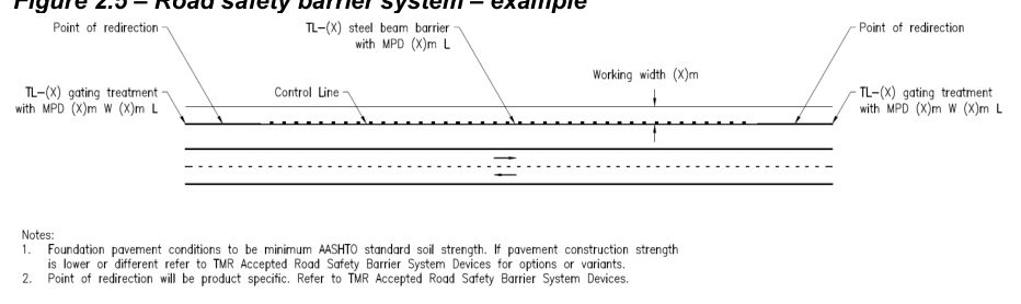
Designers are to specify barrier systems in design drawings as per the following or similar:
"TL-(X) [steel beam / wire rope / concrete] barrier [with MPD] (X)m L"
"TL-(X) [gating / non-gating] end treatment [with MPD] (X)m W (X)m L"
Drawing#
- Show control line of barrier system
- Show main elements of interest (for more complex projects show a summary table that details the main elements of interest)
- Show road safety barrier system connection locations
- Show variant locations
- Add relevant notes (such as, design foundation pavement conditions)
- Show other detail (as applicable).
| ID | Description | Control line | Start chainage | End chainage | Point of redirection¹ | Working width (m) | Variant |
|---|---|---|---|---|---|---|---|
| 1 | TL-3 gating end treatment with MP 0.5 m W 16.0 m L | MC01 | 0 | 16 | Post #3 | n/a | n/a |
| 2 | TL-3 steel beam barrier with MP 200 m L | MC01 | 16 | 216 | n/a | 1.65 | n/a |
| 3 | TL-3 steel beam barrier with MP 20 m L | MC01 | 216 | 236 | n/a | 1.65 | Base plate installation |
| 4 | TL-3 steel beam barrier with MP 50 m L | MC01 | 236 | 286 | n/a | 1.65 | n/a |
| 5 | TL-3 gating end treatment with MP 0.5 m W 16.0 m L | MC01 | 286 | 302 | Post #3 | n/a | n/a |