3Other issues#
3.1Safety in Design considerations#
The Work Health and Safety Act 2011 and Work Health and Safety Regulation 2011 impose requirements on certain duty holders.#
Road safety barrier hardware (permanent and temporary) present risks to the health or safety of persons who may be required to carry out any construction work. Such risks may be particularly pertinent to temporary devices but may also apply to permanent devices. Such risks may include (but not necessarily be limited to):
- Fragments or debris expelled during impact.
- Excess deflection or failure of a system or device to adequately contain an impacting vehicle.
- Means of access over, through or around a system or device.
- Residual energy stored in devices (especially post-impact).
3.2Deflection and working width#
Working width from impacts into barriers should be used to identify the possible intrusion into the area behind a barrier. Working width is measured from the outermost extremity on the traffic side, regardless of shape, to the furthest extremity of any part of the system or vehicle during and after the impact. Designers are recommended to adopt the largest working width value for the nominated containment level based on crash testing as per the department's accepted product datasheet or obtain from product owners. Deflection values reported in this document are typically those reported during crash testing performed under controlled conditions. Where the hazard is low enough that it does not interfere with the possible vehicle intrusion into the area behind a barrier (for example, batter), dynamic deflection is considered sufficient. Designers should be cognisant of the type of hazard(s) and the risk of vehicle and/or barrier intruding behind the barrier before deciding to use deflection value in lieu of working width. Designers are encouraged to check with product owners that these values are correct before proceeding to select site-specific design deflections. Designers need to be cognisant that the crash test deflection value is a single data point, and that in-service performance may be expected to vary. For further information, see Section 5.5.2 of Austroads Guide to Road Design Part 6. Typical working width measurements are illustrated in Figure 3.2.
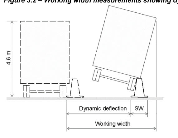
Legend: SW = System width#
Source: ASBAP (2020a) Technical Advice 20-002#
While designers may require deflection and working width values for a transition between a W-beam safety barrier and a concrete barrier, these parameters should be obtained from the product supplier, if available. In the absence of such information, a dynamic deflection of 0.2 m and a working width of 0.6 m may be used as general guidance, based on values observed in crash tests across multiple products.
3.3Steel beam barrier connection to Public Domain Single Slope Concrete Barrier#
For proprietary steel beam barriers (W-beam or Thrie-beam) connecting to a TMR Public Domain Single Slope Concrete Barrier, the Austroads SBTA 21-005 Transition should be used where permitted by the proprietary product's Technical Conditions of Use (TCU). This may be achieved by replacing the TMR SD1470 concrete terminal with Austroads SBTA 21-005 Concrete Anchor Block to facilitate connection to compatible proprietary steel beam barriers, unless otherwise specified in the proprietary product's TCU or TMR-specific conditions. The transition arrangement is illustrated in Figure 3.3.
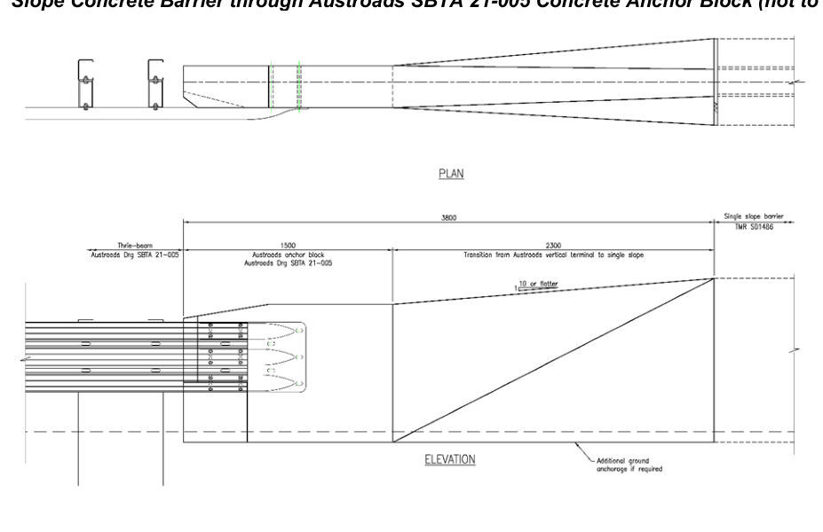
3D VIEW
For retrofit projects, proprietary steel beam barriers may be directly connected to TMR Public Domain Single Slope Concrete Barrier terminal under EDD if specified in Section 4 of this document under 'TMR conditions'. Otherwise, a Design Exception will be required.
3.4Footings and anchorages#
The person (the Designer) specifying any system relying on the resistance provided by the ground to function needs to be satisfied that the design is adequate to meet the intended level of performance for the site-specific context and ground conditions. This may necessitate for example demonstration by calculation or otherwise that the proposed footing or anchorage is at least equivalent to that used during the compliance testing in order to adequately resist lateral or longitudinal displacement as well as rotation or pull-out.
The anchors of temporary road safety barriers shall be fully removed from the work site after the designated installation period, and then the pavement surface with anchor holes shall be reinstated as per MRTS02.
3.5AASHTO soil types#
The barrier needs to resist the loads from an impacting vehicle and this action requires the soil strength to be commensurate with the strength of the soil used in testing under the MASH protocol (AASHTO). This is often an AASHTO standard soil, which is a well compacted granular soil with a CBR (California Bearing Ratio) of approximately 60. Some barriers have been tested in a MASH weak soil, which is categorised as the finer aggregate or sand that is used in concrete. The CBR for weak soils is judged to be between 8 and 10.
Refer Austroads Guide to Road Design Part 6 for further advice.#
3.6Anti-gawk screens#
The department does not maintain a list of accepted anti-gawk (or anti-debris) screens. Guidance pertaining to anti-gawk screens is provided in Section 5.3.3 of the Part 3 of the Austroads Guide to Temporary Traffic Management.
The provisions for attachments to barriers is discussed in Australian/New Zealand Standard AS/NZS 3845.1 Clause 2.5.5, which states (among other things):
"There shall be no attachment to a road safety barrier system unless it can be shown by crash testing or by assessment as a modification … that it is suitable."
Anti-gawk screens are considered to be an attachment to a road safety barrier system and as such are subject to the above provisions of the Standard. Wherever full scale crash testing is not provided then assessment (as required by AS/NZS 3845.1) is required. Such an assessment would need as a minimum to address, among other things, the provisions of AS/NZS 3845.1.
Thereafter, a second engineering assessment is required to determine whether any road safety barrier and associated anti-gawk screen is appropriate for use at a site-specific project location.
In any impact event, it is likely that some elements of the screen attachment will be displaced and will enter the workzone. Practitioners prescribing the use of anti-gawk screens should be cognisant of the consequent increase in risk to workers. Refer Section 3.1.
3.7Delineation#
Nose delineation for road safety barrier terminals, including crash cushions should be provided in accordance with the Manual of Uniform Traffic Control Devices.
3.8Standing Offer Arrangements#
There are a number of suppliers listed by the department for supply of road safety barrier systems and their components in QLD. Please refer to the department's current Standing Offer Arrangement (SOA) and Registered Suppliers List on the department website.