Single Slope Concrete Barrier#
TMR Standard Drawing 1468
9:37 AM Monday, 26 May 2025
Created:
Status*: Accepted
Status Commencement Date: Not Set
Status Expiry Date*: Not Set
Category: Longitudinal
Sub Category: Rigid
Main Material: Concrete
Ownership: Public Domain
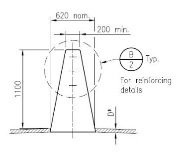
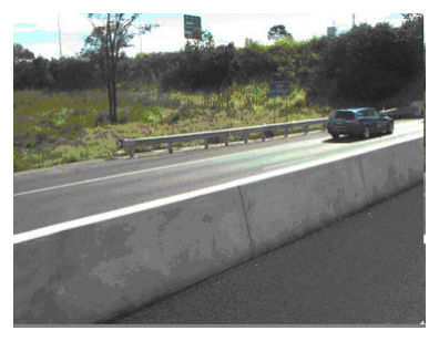
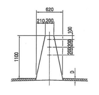
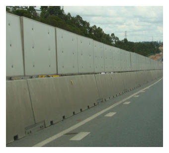
Introduction: The single slope barrier is a rigid extruded reinforced concrete barrier with a 10.8° profile. Heights may vary. AASHTO Roadside Design Guide (2011) (section 6.4.1.8) states "Concrete barrier shapes that meet the NCHRP Report 350 criteria are the New Jersey and F-shapes, the single-slope barrier (two variations in slope), and the vertical wall. These shapes, when adequately designed and reinforced may all be considered TL-4 designs at the standard height of 813mm and TL-5 designs at heights of 1067mm and higher”. An advantage of the single slope shape is that it can accommodate adjacent overlays without compromising the profile of the barrier. However, designers do need to be cognisant that overlays will reduce the effective height of the barrier and hence reduce its overall containment capacity.
Page 1 of 2
* TMR reserves the right to alter the Status and Status Expiry Date at any time. Always refer to latest version of TMR's Road Safety Barrier Systems and End Treatments document.
Gating/Non-Gating: Not Applicable
Redirective/Non-Redirective: Redirective
Permanent/Temporary: Permanent
Supplier: Public Domain
Test Level: Extruded Variant Deemed to meet NCHRP 350 TL-5 (1100mm high, anchored) (based on AASHTO Roadside Design Guide (2011) and FHWA memorandum HMHS-B64 dt. 14-Feb-2000). Refer to TMR Standard Drawing 1468 for further guidance on containment level. PCB: Pre-cast variant • Refer to Precast Concrete Barrier (PCB) data sheet • Permanent configurations for PCB shown on TMR Standard Drawing 1473
Recommended End Treatments: Any accepted permanent crash cushion (refer this document), with appropriate transition/connection. Alternatively, it is acceptable to transition to steel-beam barrier end terminal via transition (see TMR standard drawings).
Page 2 of 2
Design: Standard configurations of single slope extruded barrier are provided on TMR Standard Drawing 1468. Whilst TMR Standard Drawing 1468 nominates the single slope barrier as a median barrier, it may be used at other locations. In order to maintain the specified containment capacity, adequate footing restraint must be provided to resist overturning and lateral deflection. Austroads SBTA 21-005 Concrete Anchor Block (instead of TMR SD1470 concrete terminal) should be used to connect to compatible proprietary steel beam barriers, unless specified otherwise in the proprietary product’s TCU or TMR conditions. The minimum lengths of barrier nominated on TMR Standard Drawing 1468 apply to lengths between gaps provided for street lighting and/or expansion joints. Where there is a risk that the end of a concrete barrier can be impacted, the end must be shielded by one of: (i) an accepted connection to another barrier system, (ii) a suitable method of overlap, (iii) an accepted crashworthy crash cushion. Overlays (or lift or corrector) courses placed after initial construction of the barrier may reduce the relative/residual height of barriers and/or their profile. Designers should make provision for such future treatments when designing a barrier.
Limitations: Refer to TMR Standard Drawing 1468. Designers and project managers should be cognisant that provision of lighting within barriers introduces some additional exposure to risk: (i) Street lighting poles are likely to exist within the working width envelope. (ii) Steel cover plates shown on standard Drawing 1469 are not expected to provide test level TL-5 containment capability. Such design decisions should be documented in the design documentation.
Deflection: Whilst this barrier type is “rigid” and should exhibit zero deflection under impact, designers should be cognisant of the possibility of vehicle roll and working width when locating objects mounted on or situated behind the barrier.
References: • AS/NZS 3845 • NCHRP Report 350 • TMR Road Planning and Design Manual • Standard Drawing 1468 • Roadside Design Guide (AASHTO, 2011) • FHWA memorandum HMHS-B64 dt. 14-Feb-2000).
Department of Transport and Main Roads#
Road Safety Barrier Systems and End Treatments: Product Information Sheet#
This information sheet shall be, where relevant, read in conjunction with the manufacturer's latest manual.