Precast Concrete Barrier (PCB)#
TMR Standard Drawing 1473
9:37 AM Monday, 26 May 2025
Created:
Status*: Accepted
Status Commencement Date: Not Set
Status Expiry Date*: Not Set
Category: Longitudinal
Sub Category: Semi-Rigid
Main Material: Concrete
Ownership: Public Domain
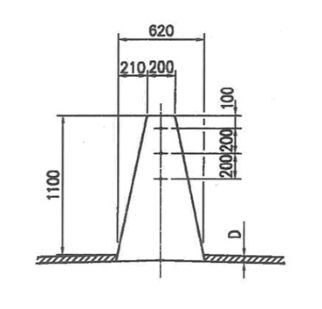
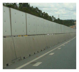
Introduction: The Precast Concrete Barrier (PCB) is a concrete barrier with a single-slope profile.
Useful Product Data: Unit length - 7250mm Unit width (base) - 620mm Unit height - 1050mm Note limitations regarding lifting: seek latest advice from TMR Structures Branch
Page 1 of 2
* TMR reserves the right to alter the Status and Status Expiry Date at any time. Always refer to latest version of TMR's Road Safety Barrier Systems and End Treatments document.
Gating/Non-Gating: Not Applicable
Redirective/Non-Redirective: Redirective
Permanent/Temporary: Permanent or Temporary
Supplier: Various
Test Level: Deemed to meet the requirements of NCHRP report 350 test level TL-3 when properly connected in accordance with QTMR standard drawing 1473.
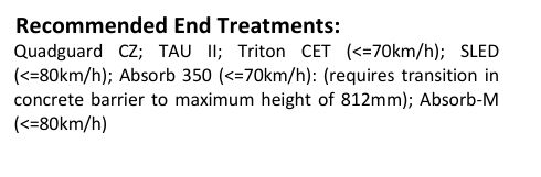
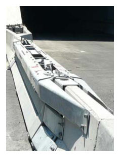
Recommended End Treatments: Quadguard CZ; TAU II; Triton CET (<=70km/h); SLED (<=80km/h); Absorb 350 (<=70km/h): (requires transition in concrete barrier to maximum height of 812mm); Absorb-M (<=80km/h)
Page 2 of 2
Design:
Minimum Length: 36 m Recommended Minimum Radius: R150m
Interaction with Kerbs
- In unrestrained configurations, the system cannot be placed adjacent to kerbs or other objects within the deflection limits of the barrier that may prevent lateral displacement.
End Treatments:
- A proprietary end treatment should be installed wherever any risk exists that the blunt end could be impacted.
- Any proprietary end treatment system must be specifically designed or adapted for use with “single slope” shape barrier and must be installed and maintained strictly in accordance with the manufacturer’s instructions.
- Barrier flare rate should not exceed 1:10.
Vehicle Roll:
- Where the hazard being protected by a barrier extends above the height of the barrier the Designer should ensure that adequate separation from the face of the barrier to the hazard is provided to allow for the roll of high vehicles (such as trucks) hitting the hazard.
References:
Deflection:
Deflection (Normal Design Domain): Measured (Crash Test) Deflections:
| Nominal Mass (kg) | Nominal Angle (deg) | Nominal Speed (km/h) | Recorded Deflection (m) | Note |
|---|---|---|---|---|
| 2000 | 15 | 100 | 0.18 | 1 |
| 2000 | 15 | 100 | 0.15 | 2 |
Actual clearance distance to workzone should be determined by risk assessment prior to installation. Designers are recommended to adopt the largest working width / deflection value for the nominated containment level.
Limitations:
- Refer TMR std. dwg. 1473 [Check for currency of revision].
- Placement of barriers and effects on surface drainage are to be considered.
Maintenance:
- Inspect units for damage after impact. Damaged units to be replaced.
- Beason et al (1989) Development of a Single Slope Concrete Median Barrier, TTI
- Barrier Systems Inc letter dated 23 March 2004
- Email correspondence on SLED transition to PCB (Saferoads, 18 December 2019)
- Australian Standard AS/NZS 3845
- NCHRP Report 350
- TMR Road Planning and Design Manual
- Main Roads Standard Drawing 1473 (rev. F)
Department of Transport and Main Roads#
Road Safety Barrier Systems and End Treatments: Product Information Sheet#
This information sheet shall be, where relevant, read in conjunction with the manufacturer's latest manual.