10Mechanical and physical requirements#
10.1General#
The mechanical and physical requirements defined in MRTS201 General Equipment Requirements apply to the TVSL sign displays and associated control electronics defined by this Technical Specification. The mounting structures supporting the TVSL sign and accessories shall be designed and RPEQ certified as appropriate for the site conditions in which they are intended to be used. Each TVSL sign must be capable of being pole mounted on a trailer and/or concrete block support structure. The structure shall be designed in accordance with the TRUM Manual, Volume 3, Part 5: Design Guide for Roadside Signs, when installed with all supporting hardware and accessories used to operate the signs. Where the sign is solar powered, the support structure shall be RPEQ designed and certified to accommodate the required solar panels. All compartments that contain any electronic components shall have an ingress protection rating IP56 in AS 60529. A certificate or letter of compliance from a NATA approved testing facility shall be made available to Transport and Main Roads upon request.
Trailer and/or concrete block support structure design documentation shall be submitted to the Principal’s representative for acceptance 28 days prior to manufacture. Hold Point 3
The sign and DP must be constructed from durable materials to enable installation and reliable operations in the intended roadside and/or tunnel environment.
Unless otherwise specified, the design life of components must be as follows:
- a)LEDs / pixels: a minimum of 5 years
- b)other electrical systems: a minimum of 10 years
- c)sign enclosure: a minimum of 20 years, and
- d)structural supports: a minimum of 40 years.
10.2Trailer#
Where the TVSL sign is mounted on a trailer, the sign and solar panel array shall have a mechanical system which allows the sign and solar panel to be safely secured to the trailer for transportation. The mechanical system shall also allow for the sign and solar panel to be safely erected on site to ensure the sign is clearly visible to motorists and that the solar panels can be adjusted to ensure optimum solar exposure and maximum energy generation anywhere in Queensland. The mechanical systems shall ensure that the sign cannot rotate due to wind gusts up to the ultimate wind speed the structure is designed. The trailer shall comply with the applicable Australian Design Rules. The trailer shall be suitable for registration in accordance with the statutory requirements of the State of Queensland. The TVSL sign trailer shall include a secure and robust mechanical assembly that will allow TVSL sign enclosure height adjustment and to allow for storage for transport.
10.2.1Static speed limit sign#
Provision for a facility for a TC1568 static sign shall be provided on the TVSL sign trailer or concrete base. This is required in cases where the TVSL sign display has blanked for any reason, that a static sign speed as defined by the TGS will always be available.
To improve safety outcomes at road works, a static regulatory speed limit sign will be displayed to ensure motorists continue to obey the safe speed limit, in the event of the sign display failure.
The static sign may be inbuilt as an integral component of the TVSL mechanical assembly (trailer or concrete block mounted) or provided separately but co-located with the respective TVSL sign. The static sign shall be compliant with the requirements of the Queensland MUTCD.
10.2.2Flashing Yellow Alert Light#
Each TVSL sign shall be fitted with a Flashing Yellow Light which complies with the following requirements:
- a)Securely mounted to the top centre of the TVSL sign rear surface
- b)utilises Yellow LED technology that complies with the Illumination and Chromaticity requirements of AS 5156
- c) flashes once every second, and
- d) light emitted by the flashing yellow light shall be obscured from view by oncoming traffic and only observable from the rear side of the TVSL sign.
10.2.3Dimensions#
The trailer dimensions shall take into consideration the sizes of the individual components required to be supported by the trailer. The dimensions shall be within the Queensland regulation limits as detailed below.
The trailer shall have a flat top and a minimum ground clearance equal to the height of the trailer wheel axle.
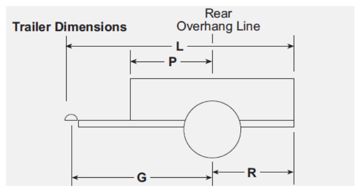
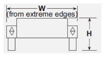
Referring to Figure 10.2.3 above, the trailer dimensions shall comply with the following:
- Width (W) shall be 1.5 m or less
- Height (H) shall be 2.4 m or less, and
- Length (L) shall be 3 m or less.
The trailer shall be compliant with the following:
- Transport Operations (Road Use Management) Act 1995
- Transport Operations (Road Use Management – Vehicle Standards and Safety) Regulation 2021, and
- Transport Operations (Road Use Management – Mass, Dimensions and Loading) Regulation 2005
The trailer shall be positioned at least 0.5 m offset from the edge of the road.
10.2.4Wind loading#
All components of the TVSL sign shall be designed and certified by a suitably qualified RPEQ to ensure that it will maintain its intended orientation and position when subjected to the wind loading conditions of the region in which the TVSL is intended to be deployed, in accordance with AS/NZS 1170.2.
The weight of the trailer shall be reviewed in accordance with the relevant safety requirements to minimise roadside hazard for traffic.
10.2.5Storage compartment#
The storage compartment shall incorporate separate battery, hoist control and general storage compartments. In order to provide a high standard for occupational health and safety (OH&S), the compartments shall not protrude more than 30 mm above the trailer deck height. A minimum of one storage compartment for general use with a minimum of 0.1 m³ capacity shall be provided.
All storage compartments shall be key lockable and comply with applicable OH&S regulations and requirements.
Any storage compartments shall have Ingress Protection (IP) rating of 56 in accordance with AS 60529.
10.2.6Stabilisers#
The trailer shall be suitably designed to ensure stability of the TVSL sign and associated hardware (i.e., solar panels) when positioned out on site. The type of stabilisers shall:
- a) allow for swivel
- b) be located on the 4 corners of the trailer, have fixed location on all 4 corners engineered to stabilise trailer and sign with sign fully extended while meeting wind loading conditions
- c) be wind-down and readily stowable for safe and secure towing
- d) have a load rating sufficient for levelling of the trailer, and
- e) have a locking mechanism with removable handles and secure drive nuts.
10.3Sign enclosure#
The sign enclosure must house the sign displays and associated control electronics and comply with the relevant requirements of MRTS201 General Equipment Requirements.
10.3.1Sign enclosure dimensions#
The size of the speed limit display shall be as defined in AS 1744. The size of the TVSL sign shall be as specified in the contract. The enclosure shall be sufficiently sized for the size of the speed limit sign display.
The total external dimensions of the housing shall not be more than 150 mm larger than the required sign face.
The sign numeric displays must be based on a series of pixels forming a dot matrix display system. The horizontal and vertical pitch of the pixels in the matrix must be the same. The apparent width of all displayed elements including text must match the respective sign display defined in the Queensland MUTCD.
The TVSL LED sign display component must be fully self-contained and capable of being removed and installed on site by hand via the access door(s) for maintenance.
The display must be physically capable of displaying speeds from 40 km/hr up to the 110 km/hr for the TVSL site in 10 km/hr increments. The actual speed range for each site must be confirmed with the Principal during the commissioning activities and retained as part of the non-volatile information stored in the DP. Only those frames permitted to be displayed at the site of installation shall be programmed into the DP.
10.3.2Doors#
Access doors and hatchways required for maintenance, configuration and stowage shall be secured via a key lock mechanism. All doors and hatchways shall prevent any moisture ingress into the compartments and have ingress protection rating of IP56.
10.3.3Front cover#
A protective front cover must be fitted to the TVSL sign enclosure to form a viewing window. The front cover material must be a single, clear Lexan® sheet or equivalent, and have a non-reflective finish.
The sheeting must be manufactured from sign-grade material SG300 with a thickness at least equal to that recommended by the manufacturer, with an absolute minimum of 4.5 mm. The viewing window must be such that when installed, the sides and bottom edges of the display face are fully visible at viewing angles of ± 45° (horizontal) and ± 60° (vertical) to the axis perpendicular to the front plane of the display.
The front cover must include a clear, non-reflective polycarbonate front screen. Suitable means must be provided to demist the front screen.
The front cover must be able to be removed for maintenance without requiring removal of internal components.
The front cover retention and seal design must allow for thermal expansion properties of the front cover material. The front cover surrounding framework and cover strips must provide the required weather proofing and strength for both positive and negative wind pressures and, where applicable, tunnel deluge systems.
The front covers shall be fastened to the sign display enclosure through security screws or other secure fastening methods.
In respect to the front viewing window, where installed, shall be made from anti-glare and U.V. stabilised polycarbonate with a minimum thickness of 4.5 mm.
10.3.4Enclosure material and coatings#
The materials used for the trailer mounted TVSL enclosure shall be aluminium as specified in AS 5156, suitably reinforced and/or braced to facilitate the installation and continued operation of the unit in the intended application.