
7Communication requirements#
7.1General TVSL communications layout#
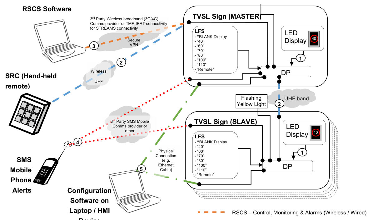
RSCS Software · TVSL Sign (MASTER) · 3rd Party Wireless broadband (3G/4G) Comms provider or TMR IPRT connectivity for STREAMS connectivity · LED Display · 3 · LFS · “BLANK Display · “40” · “60” · “70” · “80” · “100” · “110” · “Remote” · Secure · 40 · VPN · 1 · 2 · Wireless · DP · SRC (Hand-held remote) · UHF · Flashing Yellow Light · UHF band · 2 · TVSL Sign (SLAVE) · 3rd Party SMS Mobile Comms provider or other · LED Display · 40 · LFS · “BLANK Display · “40” · “60” · “70” · “80” · “100” · “110” · “Remote” · 4 · Physical Connection · 1 · DP · SMS · Mobile · (e.g. Ethernet · 5 · Cable) · Phone · Alerts · Configuration Software on Laptop / HMI · RSCS – Control, Monitoring & Alarms (Wireless / Wired) · Device · SMS – Alarms ONLY (Wireless) · SRC – Control ONLY (Wireless) · Configuration – Control, Monitoring, Alarms & Administration (Wired)
7.1.1Device Processor (DP) and LED display (on the same trailer / concrete block)#
The communications system shall be tamperproof and fully enclosed. Communication between the local DP and LED sign display shall be via a direct wired connection. The communications shall be encrypted. Messages transmitted between the DP and the LED display shall be completed within 50 ms of being sent. Refer to item 1 in Figure 7.1 above.
7.1.2Master, Slave DP(s) and SRC(s)#
Communication between the Master, Slave DP(s) and SRC(s) shall be via a local wireless communication technology, such as Ultra-High Frequency (UHF) radio band or other reliable wireless technology. Wireless communications shall also be encrypted. Refer to item 2 in Figure 7.1 above.
The SRC and Master DP shall communicate with 99.9% reliability over point-to-point ranges of greater than 30 m.
The Master and Slave DP(s) shall communicate with 99.9% reliability over point-to-point ranges of greater than 500 m. This will account for communications to multiple Slave DP(s)—some of which are separated from the Master DP at a maximum distance of 500 m at a site.
Where 2 TVSL signs are configured as a Master and Slave, periodic one-second communications (time-out period) polling messages shall be transmitted for the purposes of establishing whether a loss of communications has occurred. When loss of communications has been detected, an alert shall be raised on both signs.
Where a SRC has requested a change of speed on a TVLS sign DP, the speed change shall be completed within 250 ms of the request – i.e., the respective DP’s display shall energise the requested frame LED pixels.
Any radio frequency communications antennas shall be positioned at the highest point on the TVSL sign to make effective use of available signal gain and avoid line of sight signal attenuation by objects such as concrete barriers and shrubs.
Communications shall be in accordance with Australian Communications and Media Authority (ACMA) requirements.
7.1.3Configuration software and DP#
Communications between the configuration software and the DP shall be over a direct 10/100base-T Ethernet connection. The communications cable shall be CAT5 and pre-terminated with EIA-568A RJ45 connectors. The IP address of the configuration laptop or other HMI device shall be able to be set to the same range of the DP’s maintenance port network address. Refer to Table 7.1.3 below for example IP settings. Once an initial configuration connection has been established, the IP address settings shall be able to be changed from the defaults.
| DP maintenance Ethernet port settings | Configuration laptop or HMI device Ethernet port settings | |
|---|---|---|
| IP address | 192.168.1.100 | 192.168.1.101 |
| Subnet mask | 255.255.255.0 | 255.255.255.0 |
| Default gateway | Not required | Not required |
If an existing remote RSCS connection is currently in session when the LFS is changed to the 'Blank Display' mode, the DP shall provide notification to the RSCS software logged on user that a local configuration connection is in session and any remote RCSC communication control requests will be ignored. After the local session has been disconnected and the LFS is returned to the 'Remote' mode position, any remote session will be immediately re-established (only after an RSCS software confirmation dialog is raised to the RSCS operator for authorisation to proceed with the previously executed TGS plan and associated parameters), all data will be resynchronised between the connected DP (or pair) and RSCS software.
During an existing configuration maintenance port session, monitoring and alarms shall continue to be transmitted to the interrupted RSCS Software communications session. Refer to item 5 in Figure 7.1 above.
Direct connections are used to allow onsite maintenance and diagnostic functions to be carried out if required using TVSL configuration software through the maintenance port onsite at the Device Processor (DP) within the TVSL sign.
7.2Remote site communications#
7.2.1DP and RSCS#
There are essentially 2 remote site methods which can be used to allow communications between the DP and the RSCS.
7.2.1.1STREAMS as the RSCS#
The DP, if required by Transport and Main Roads, can be connected to STREAMS. The supplier of the DP shall ensure that it is fully compatible with the version of STREAMS at the time of delivery and submit a Transmax STREAMS Certificate of Support to Engineering and Technology section of Transport and Main Roads.
Network communications between the DP and STREAMS shall be in accordance with the requirements of MRTS245 ITS Telecommunications Network (ITS TN).
7.2.1.2External systems as the RCSC#
Communication between the DP and a laptop or desktop computer running the RSCS software shall be 10/100Base-T Ethernet over a connection such as third party wireless 4G / 5G mobile, ADSL or optical fibre. The carrier selected shall have sufficient and reliable coverage at the project site. Refer to item 3 in Figure 7.1 above.
The DP shall have a dedicated RJ45 10/100Base-T Ethernet port for the purposes of remote communications to the RSCS. This port will be used as the primary remote communications connection point for any wireless third-party modem, Ethernet switches or other devices required as per the remote communications design.
All messages transmitted from the RSCS software to the Master DP embedded firmware shall not exceed 5 seconds.
All messages transmitted from the Master DP to the RSCS software shall also not exceed 5 seconds.
Setup and ongoing provision of the mobile service required is the responsibility of the contractor who owns the TVSL sign.
All insecure protocols services, such as telnet, HTTP, etc., shall be able to be disabled on the DP to prevent any unauthorised communications terminal access to the local DP.
Should maintenance and diagnostic functions be required to be undertaken on the DP, then secure communication protocols such as SSH, HTTPS shall be supported.
Utilising a VPN will ensure that any communications over the internet is secure and unauthorised access is prevented.
All communication over third party communications network shall utilise a secure connection, such as a Virtual Private Network (VPN).
7.2.2DP and critical alert SMS notification system#
Communication between the DP and a mobile phone for the purposes of the transmission of critical alert SMS notifications as defined in Clause 9.2 below shall be via a third-party SMS mobile service provider. The telecommunications carrier selected shall have sufficient and reliable coverage at the project site. Refer to item 4 in Figure 7.1 above.
7.3Communications timeout#
For general operations of Master / Slave pair, if a slave does not receive an acknowledgement from the master within one second, the slave shall be blanked. If the Master does not receive an acknowledgement from the slave within one second of message transmission, then the slave shall be blanked (i.e., a blanking message will be transmitted to the slave). Refer to Appendix B for a summary of TVSL sign blanking conditions under this Technical Specification.
All timeout periods shall be software configurable with ranges and default values stated in Appendix A. This is required to allow a refinement of timeout periods to reflect current practices and scenarios.
For BLANK display mode, if configuration software session remains inactive for a period as defined in Appendix A, then the user session will be terminated and the user will need to re-logon and establish another session.
If the Master TVSL sign DP detects a loss of communications with the RSCS, then both the Master and Slave shall be blanked.
The DP must be capable of monitoring loss of communications with the RSCS and timeout after a specified period. When the Master DP LFS is in the 'REMOTE' mode, expiry of this time period must cause the DP to blank all physically connected signs (refer Appendix B). This period shall be a configurable parameter and is denoted 'Session timeout'. The range and factory default settings of session timeout are shown in Appendix A. The DP must also be capable of monitoring communications with the signs connected to it and timeout after a specified period when such communication is lost. Communications timeout check shall be performed periodically as shown in Appendix A. When the Master LFS is on any other mode, the session timeout check with the RSCS shall be ignored.
7.4Communications identifiers#
The SRC, Master and Slave DPs shall each have a configurable unique communications ID.
Each Master and Slave pair combination may have a unique site pairing ID for the purposes of communication with the RSCS software.
Communications messages between the DPs (Master and Slave) and SRC shall include a checksum unique to each TVSL roadwork site that is based on the message information exchanged to ensure integrity of the communication is upheld. The checksum shall be available for confirmation by the RSCS that the permitted frames at each TVSL site are the same as those stored within the RSCS software. The checksum shall be verified periodically and recomputed each time the permitted frames are changed and/or that the DP is reset/rebooted.
7.4.1Device Processor (DP) ID#
Each TVSL sign DP shall have a unique factory hardware ID which cannot be changed. This ID will be referenced by DPs of other TVSL signs, such as those in a Master / Slave pair arrangement. Any communications messages transmitted by a DP shall embed the DP's respective ID. A physical label displaying this ID must be clearly visible on the TVSL sign trailer / concrete block.
7.4.2SRC ID#
A unique SRC ID shall be configured on a SRC through an on-board settable dipswitch. This ID will be referenced by the Master TVSL DP.