Technical requirements#
6.1Device Processor (DP) requirements#
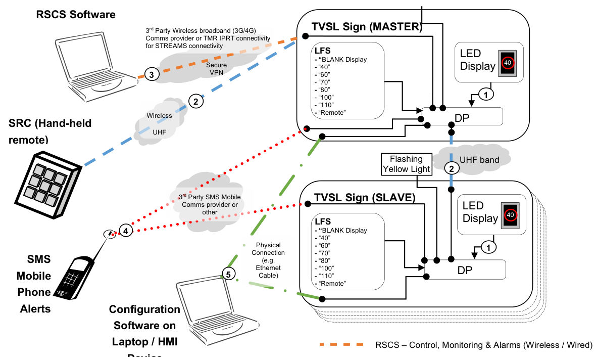
Each TVSL sign shall have a DP and it shall:
- a)conduct all processing associated with the communications support for paired slave sign(s)
- b)ensure that the requested speeds are displayed on the TVSL sign LED display and carries out all associated processing and monitoring functions
- c)monitor, log and report the operation of each connected sign display individually
- d)allow the TVSL sign to be controlled individually or as part of a pair
- e)be capable of storing up to 255 frames in its non-volatile memory. The full list of frame designations is captured in Appendix C - Full listing of speed limit frame designations
- f)command signs to display only the allowable frame combinations for that respective site as defined by the TGS
- g)allow local automatic reset of sign displays and the DP itself such as via watchdog(s)
- h)be capable of automatically dimming connected signs based on the average of the light sensor outputs. Automatic dimming of the sign occurs to increase luminance and hence conspicuity. The dimming levels and factory default settings are shown in Appendix A. Automatic dimming is not to be used for the purpose of extending battery life
- i)accept / reject valid or invalid commands made by the SRC, RSCS, configuration software or connected Master / Slave DPs
- j)allow a unique electronic identification for each DP to be configured
- k)electronically verify with the connected sign display that the displayed speed is consistent with the speed originally requested and permitted
- l)upon power up, ensure the sign LED display shall be initially blank and a valid frame is only displayed after all internal tests have passed, and
- m)accept an analogue input from a Local Facility Switch (LFS).
Additional information and functionality of the DP required is described in the following clauses.
6.2Permissible Frames (PF)#
Each TVSL sign DP shall be configured to store only those frames permitted to be displayed as defined in the approved TGS for the site in which they are operating (refer the list of frame designations in Appendix C). This will be achieved through the RSCS or configuration software referred to in this Technical Specification. The DP shall ensure that only permitted frame displays in the signs.
In addition to the other logged events detailed in Clause 9.1 below, the DP shall generate, log and report an alarm if a frame display request by the RSCS or SRC is for non-permitted frames.
The DP shall allow:
- a)the configuration and RSCS software to read and write its permitted frame (PF), and
- b)the display of stored frames only when requested by the SRC or RSCS.
This includes the default, maximum and minimum speeds allowed at the respective TVSL site.
Where TVSL signs are deployed in a pair, both TVSL sign displays shall only display the same permissible frame.
TVSL signs are not required to display lane closure symbols.
6.3Frame display time#
The minimum display duration of each frame shall be configurable and accessible via the configuration software via the maintenance port. The time range and factory default settings are shown in Appendix A.
6.4Flashing display control#
The DP shall command inner rings of the annulus to flash when speeds other than the site’s default speed are displayed. The outermost ring shall remain on whilst the inner rings are flashing. Where 2 or more signs are connected to the same DP, the flashing elements of all signs at that site must flash in synchronisation. The flash rate and display cycle shall be configurable and factory default settings are shown in Appendix A.
6.5Watchdog#
The TVSL sign display and DP must each monitor the state of its respective processor and blank the respective display(s) if processor failure occurs.
The DP shall generate an alarm and perform a graceful power shutdown all signs if the integrity of the firmware or configuration is compromised.
6.6Global Positioning System (GPS)#
Each TVSL sign shall be fitted with a GPS receiver. The on-board GPS receiver shall monitor the location in 3 dimensions (Latitude, Longitude and Altitude) of each sign and also synchronise the TVSL DP internal clock. Each TVSL sign shall have provision for the numeric display to be synchronised by means of the sign's DP internal clock and the Master / Slave arrangement. The DP shall provide an alarm if a sign is moved beyond a 30 m radius of its installed position. This may be achieved using a virtual perimeter or ‘geo-fence’.
6.7Directional compass capability#
Each TVSL sign may have the ability to discern the installed directional orientation (yaw) and whether any subsequent change in direction has been detected, through the use of a Magnetometer Inertial type sensor. The accuracy of the compass shall be at least ± 1 degree of yaw after calibration. An alarm shall be raised should the orientation be changed by ± 20 degrees from the installed position.
6.8Turning motion sensor#
Each TVSL sign may have the ability to discern whether the unit’s position has been altered from the installed position through the use of gyroscope.
6.9Short Range Controller (SRC)#
The local method of control is via a hand-held SRC wireless communications device. The following requirements shall apply to the use of the SRC:
- a)Once TVSL signs have been configured for a particular construction site, they shall be capable of operating with the following modes only:
- i.Mode 1 Work Mode – During Construction Hours Display
- ii.Mode 2 No-Work Mode – After Construction Hours Display, and
- iii.Mode 3 Blank Mode – Blank Display.
- b)Use ‘code hopping’ or ‘rolling code’ technology to prevent unauthorised use of the signs through methods such as “replay attacks”.
- c)Have a unique ID (refer to Clause 7.4 below) that is transmitted with each mode change request.
- d)The SRC shall have 3 programmable, and clearly labelled buttons to reflect the above modes, and be visually identified as shown in Table 6.9.
- e)When a SRC mode activation button is pressed and held for 2 seconds, then an LED indication within the button shall be illuminated to confirm to the Site Supervisor the desired mode of operation.
- f)If an SRC mode activation button LED is illuminated and the SRC Transmit Button is pressed and held for 2 seconds a control message shall be transmitted to the Master DP.
- g)Should a RSCS mode change request occur at the same time as the mode change request from an SRC, the SRC mode request shall have priority and the RSCS mode request shall be ignored (refer to Table 5.3 TVSL Control Methods).
- h)SRC batteries shall last for at least one year without requiring to be replaced.
- i)Where a Master and Slave DP pair has been configured, the SRC shall only communicate with the relevant Master.
- j)The DP may have the ability to deactivate a SRC from controlling the TVSL sign (e.g., due to lost or damaged SRCs) through the TVSL configuration software, RSCS software, and
- k)The physical buttons of the SRC are to be sufficiently spaced apart from each other so as not to prevent accidental incorrect activation.
| SRC | Control mode | Button label text | Button selection 5 mm LED colour |
|---|---|---|---|
| Button 1 | 1 | WORK | GREEN |
| Button 2 | 2 | NO-WORK | AMBER |
| Button 3 | 3 | BLANK | RED |
| Button 4 | N/A | TRANSMIT | N/A |
6.10TVSL Sign Master / Slave pairing#
Where 2 signs are installed in a pair, one DP from the pair shall act as the Master controller for both signs and the other as the Slave. This shall be achieved through the setting a TVSL sign to operate either as a Master or Slave via the connected RSCS or configuration software described in Clauses 8.1 or 8.2 below respectively.
6.10.1Master#
Where a DP is set to operate in Master mode, all secure remote communications requests from a SRC or RSCS for a configured Master and Slave pair shall be accepted by this DP. The DP shall be configured to simultaneously control up to a maximum of 5 slave DPs, each with the same control message including the unique slave DP ids.
6.10.2Slave#
Where a DP is set to operate in Slave mode, all remote communications from any SRC or RSCS for a configured Master and Slave pair shall be ignored.
6.11Local Facility Switch (LFS)#
Each TVSL sign shall have a physical Local Facility Switch (LFS) for onsite backup control. The LFS will allow the manual setting of the following modes:
- 1.‘BLANK Display’ Mode: Blank the TVSL Sign Display, allow maintenance port connections
- 2.‘Display 40’ Mode: Displays ‘40’ on the respective TVSL Sign LED display panel
- 3.‘Display 60’ Mode: Displays ‘60’ on the respective TVSL Sign LED display panel
- 4.‘Display 70’ Mode: Displays ‘70’ on the respective TVSL Sign LED display panel
- 5.‘Display 80’ Mode: Displays ‘80’ on the respective TVSL Sign LED display panel
- 6.‘Display 100’ Mode: Displays ‘100’ on the respective TVSL Sign LED display panel
- 7.‘Display 110’ Mode: Displays ‘110’ on the respective TVSL Sign LED display panel, and
- 8.‘REMOTE’ Mode: Sets the TVSL Sign to accept remote communications from SRC and RSCS.
Where selection on the LFS has been made, the DP shall wait for 3 seconds prior to activating the selected mode. This will ensure no other mode is inadvertently activated when physically toggling through the available options.
The DP shall allow configuration of each LFS selection such that only allowable display frames can be invoked per site.
The physical LFS switch shall be key-lockable to prevent vandalism and unauthorised control.
The purpose of a LFS is to provide manual local override to blank the sign display.
When a mode has been activated, the DP shall store the current GPS, compass bearing (if available) and inclination angle (if available). These values will represent the installed position for the purposes of the DP detecting and providing notification on any subsequent movement due to unauthorised tampering, vehicular incident, wind, accidents and other reasons.
6.11.1‘BLANK Display’ mode#
Where BLANK mode is selected on an LFS, the following requirement shall apply:
- a)Whilst this mode is selected at the particular TVSL sign, any subsequent display requests from a RSCS Software session or SRC device(s) shall be ignored by the DP (applies to Master and Slave).
- b)If there is an established RSCS software session, monitoring and alarms from the Master DP shall still be transmitted to the RSCS Software.
- c)Critical alert SMS-based notifications shall still be transmitted by the DP (applies to Master and Slave).
- d)The TVSL sign shall remain powered up.
- e)Activate the dedicated maintenance port (the maintenance port is deactivated in all other LFS modes).
- f)Where 2 signs have been configured as a Master / Slave pair, selecting the LFS to ‘BLANK Display’ on one TVSL sign shall NOT blank the other paired TVSL sign, and
- g)The LFS shall be designed as fail-safe operation and as such should it fail or be disconnected, ‘BLANK Display’ mode will be activated.
Appendix B summarises the conditions at which the TVSL sign display is blanked.
6.11.2‘Display 40’ mode#
Irrespective of whether Master / Slave designation, this mode will allow the speed limit of ‘40’ to be continuously displayed on the respective Master or Slave TVSL sign. Only when the LFS mode selector is moved to another position will the sign display be changed.
6.11.3‘Display 60’ mode#
Irrespective of whether Master / Slave designation, this mode will allow the speed limit of ‘60’ to be continuously displayed on the respective Master or Slave TVSL sign. Only when the LFS mode selector is moved to another position will the sign display be changed.
6.11.4‘Display 70’ mode#
Irrespective of whether Master / Slave designation, this mode will allow the speed limit of ‘70’ to be continuously displayed on the respective Master or Slave TVSL sign. Only when the LFS mode selector is moved to another position will the sign display be changed.
6.11.5‘Display 80’ mode#
Irrespective of whether Master / Slave designation, this mode will allow the speed limit of ‘80’ to be continuously displayed on the respective Master or Slave TVSL sign. Only when the LFS mode selector is moved to another position will the sign display be changed.
6.11.6‘Display 100’ mode#
Irrespective of whether Master / Slave designation, this mode will allow the speed limit of ‘100’ to be continuously displayed on the respective Master or Slave TVSL sign. Only when the LFS mode selector is moved to another position will the sign display be changed.
6.11.7‘Display 110’ mode#
Irrespective of whether Master / Slave designation, this mode will allow the speed limit of ‘110’ to be continuously displayed on the respective Master or Slave TVSL sign. Only when the LFS mode selector is moved to another position will the sign display be changed.
6.11.8‘Remote’ mode#
Where Remote mode is selected on the LFS, the following requirements apply:
- a)The Master DP shall accept control communications from a hand-held SRC device (s) only if the SRC device(s) are configured as being authorised to control the respective Master DP.
- b)The Master DP shall accept control communications from a PC / laptop running the RSCS software over a wireless or hardwired connection.
- c)The Slave DP shall accept control communications from a configured Master DP if it is configured as part of this Master and Slave TVSL pair.
- d)The Master DP shall transmit all messages associated with all monitoring and alarming categories under this Technical Specification.
- e)Critical alert SMS-based notifications shall be transmitted by the respective DP (Master and Slave).
- f)With the exception of Critical alert SMS-based notifications, where configured as part of a pair, all communications from a Slave DP shall be to its Master DP ONLY.
6.12Maintenance communications port#
A separate dedicated maintenance communications port shall be provided at the TVSL Sign DP to allow a PC or laptop running the supplied TVSL sign configuration software to perform all maintenance and diagnostic functions on the respective TVSL sign.
The communications port shall be a dedicated 10/100Base-T Ethernet (RJ45) port.
If at any time during an existing maintenance port configuration session, an attempt is made to select an LFS mode other than the ‘Display Blank’ mode, then the DP shall ignore the LFS request(s) and provide a visual notification to the maintenance operator such as a popup alarm(s) on the configuration software. The DP shall continue to ignore any LFS control mode change requests until such time, the existing maintenance port configuration session has been terminated.
Disconnection of the configuration software laptop from the maintenance port must not require further interaction from the user, nor in anyway interrupt operation or require rebooting of the DP.
Upon disconnection of the direct connection between the configuration laptop and the DP, the existing maintenance port configuration session shall be immediately terminated within the DP and “Blank Display” Mode re-initiated.