
5Functional requirements#
5.1General operation#
The use of the TVSL signs shall be in accordance with Chapter 2 of the Guideline – Traffic Management at Works on Roads (and have the capability of operating as either:
- Single units as in Figure 5.1(a), or
- a Master and Slave Pair as in Figure 5.1(b)
as defined by the approved Traffic Guidance Scheme (TGS).
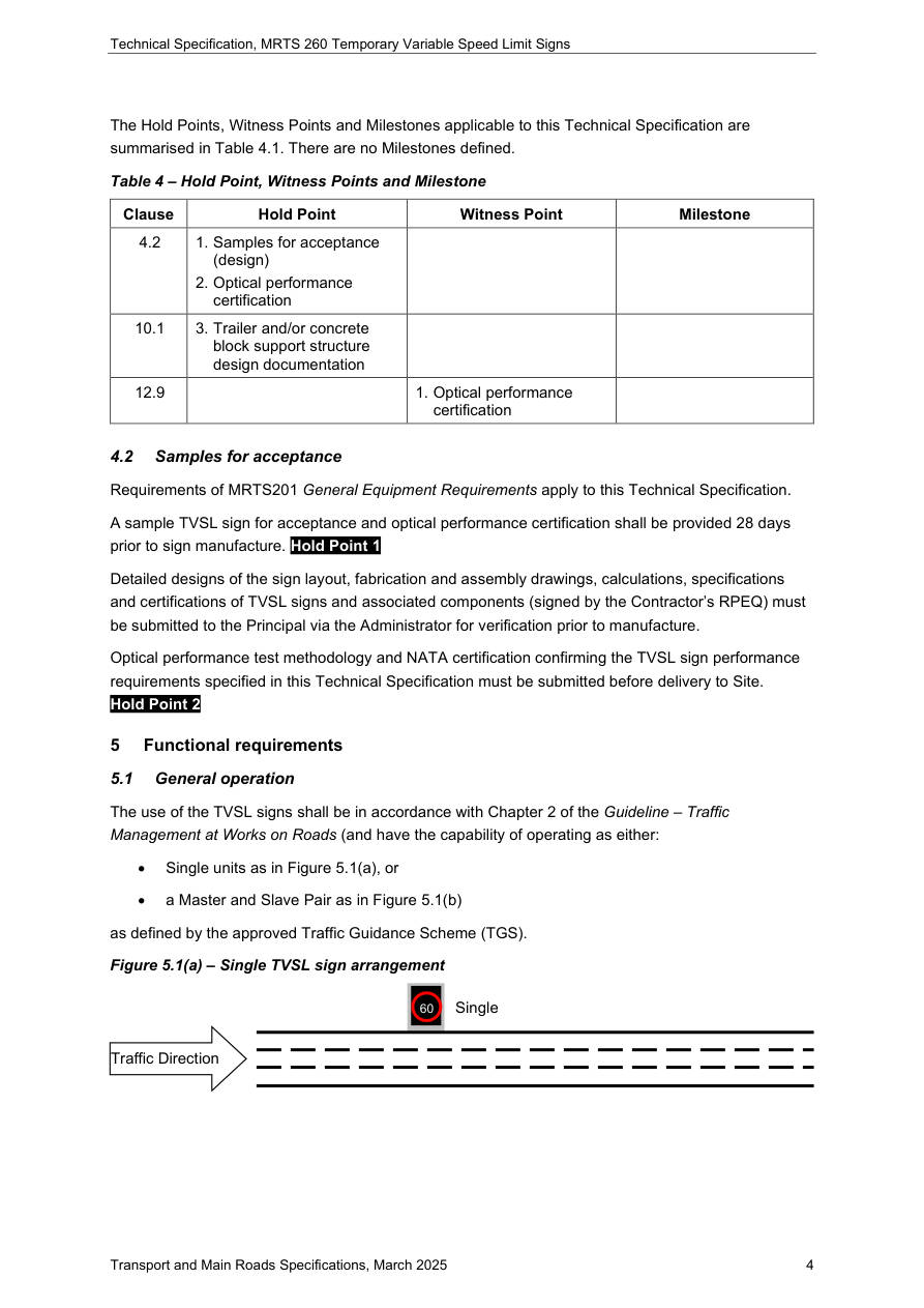
60 · Single · Traffic Direction
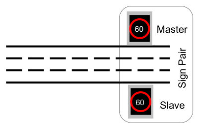
60 · Master · Sign Pair · Traffic Direction · 0 60 · Slave
5.2Reliability#
All TVSL system shall have a minimum of 99.9% system operating reliability.
5.3Functional control methods#
The TVSL shall be operated through the listed methods in the Table 5.3 below.
| Control method | Priority |
|---|---|
| Local Facility Switch (LFS) – Where onsite personnel take manual control of the TVSL Sign | 1 (Highest) |
| Maintenance Port – Onsite at the TVSL Sign | 2 |
| Local site hand-held Short-Range Controller (SRC) – Where onsite personnel take local control of the TVSL sign | 3 |
| Remote Sign Control System (RSCS) – Where offsite personnel operate the TVSL Sign. This could also be local to the site but via remote communications. | 4 (Lowest) |
5.4Key TVSL operational components and general function#
Figure 5.4 shows the key components associated with TVSL.
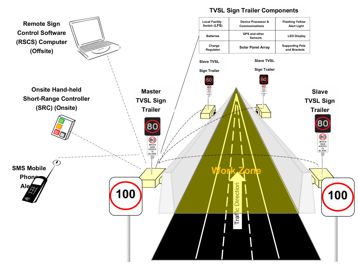
Remote Sign · Control Software (RSCS) Computer (Offsite) · Onsite Hand-held Short-Range Controller (SRC) (Onsite) · Master TVSL Sign Trailer · SMS Mobile Phone Alerts · TVSL Sign Trailer Components · Local Facility Switch (LFS) · Device Processor & Communications · Flashing Yellow Alert Light · Batteries · GPS and other Sensors · LED Display · Charge Regulator · Solar Panel Array · Supporting Pole and Brackets · Slave TVSL Sign Trailer · Slave TVSL Sign Trailer · 60 · 60 · Slave TVSL Sign Trailer · Work Zone · Traffic Direction · 100 · 100
Each component carries out specific functions associated with the operation of the TVSL sign and can be broadly categorised into hardware or software.
5.4.1Hardware#
Table 5.4.1 briefly describes the function of each hardware component.
| Item | Brief functional description | Clause |
|---|---|---|
| Device Processor (DP) | The DP is a hardware component embedded into the TVSL Sign Trailer. The function of it is to provide the internal processing and communications capability for the TVSL sign trailer | 6.1 |
| Movement Sensors | The function of the GPS, compass and gyroscopic movement sensors is to provide periodic monitoring to detect and alert when the TVSL sign has moved from the installed position due to any number of reasons, including accident, theft, slippage and high wind | 6.6, 6.7 and 6.8 |
| Short Range Controller (SRC) | The function of the SRC is to provide 3 modes of operation only–for short range wireless local control mechanism for a TVSL sign or pair of signs at a roadwork site. The SRC is a hand-held device with limited functionality. No administration or configuration operations can be carried out with this device | 6.9 |
| Local Facility Switch (LFS) | The function of the LFS is to provide “Remote” and “Blank Display” selections for remote control and to set the blank the TVSL sign display respectively | 6.11 |
| Flashing Yellow Alert Light | The function of the flashing yellow alert light is to notify onsite personnel that a TVSL sign has experienced any of the predefined critical failure conditions | 9.2 and 10.2.2 |
| Trailer / Base | The function of the trailer or other base, such as a concrete plinth, is to secure in place the TVSL sign and associated components | 10 |
| Solar Panel Array | The function of the solar panel array is to charge the TVSL battery storage capacity | 11.1 |
| Batteries | The function of the battery bank is to provide sufficient storage for the continuous operation of the TVSL sign during periods of limited sunlight or due to failure of the charging circuitry | 11.1 |
| LED Display | The function of the LED display is to illuminate the array of LEDs (Annulus and numeric characters) to display a stored permissible speed limit frame when requested by the DP. | 12 |
5.4.2Software#
There are also several software components associated with the TVSL sign as described below in Table 5.4.2.
| Item | Functional description | Clause |
|---|---|---|
| Remote Sign Control System (RSCS) Software | The function of the RSCS software is to control, monitor, administer and manage the connected TVSL signs at roadwork sites using secure wireless communications | 8.1 |
| Maintenance / Configuration Software | The function of the maintenance or configuration software for the TVSL sign is to allow the direct connection of a laptop or other compatible device for the purposes of running fault diagnostics, extraction of log local files, local administration tasks and other configuration functions | 8.2 |
| Short-Range Controller (SRC) Firmware | The function of the SRC firmware is to provide the executable programmatic script or program which can be run on the SRC hand-held device to undertake the required limited functions, with a high level of rigour and fidelity | 8.3 |
| DP Firmware | The function of the DP firmware is to provide the executable programmatic script or program which can be run on the DP’s internal operating system to undertake the required DP functions | 8.3.1 |