5Advisory Bicycle Lanes#
5.1Design specifications#
If the site is appropriate for the implementation of ABLs, then there are a number of design issues that need to be considered including:
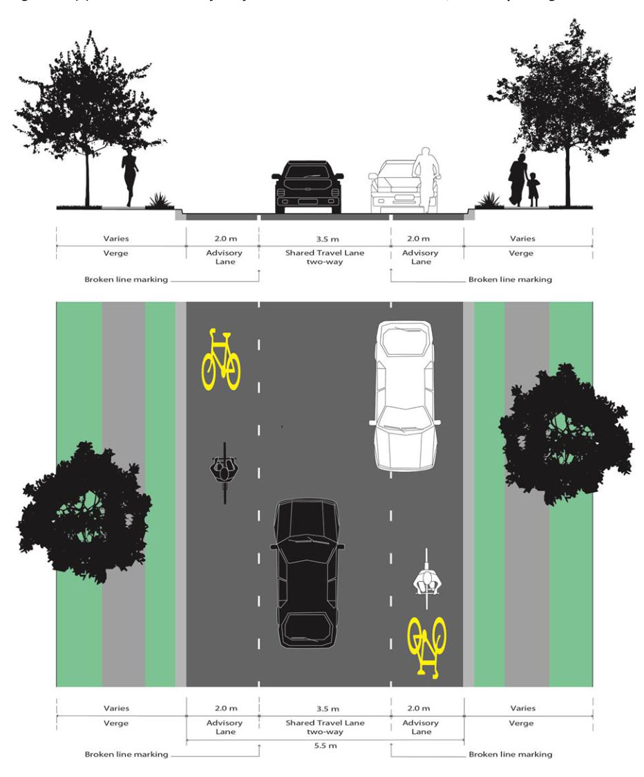
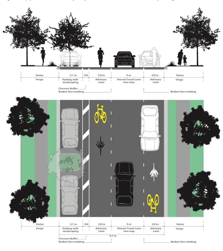
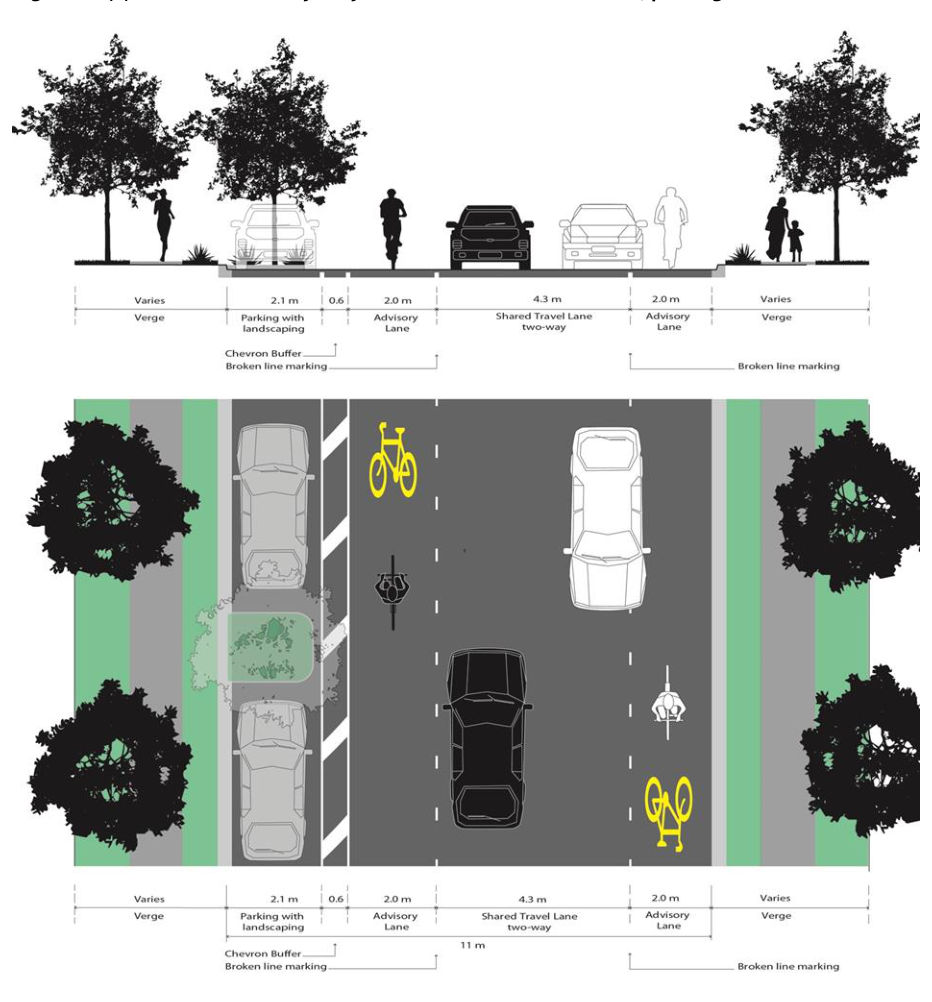
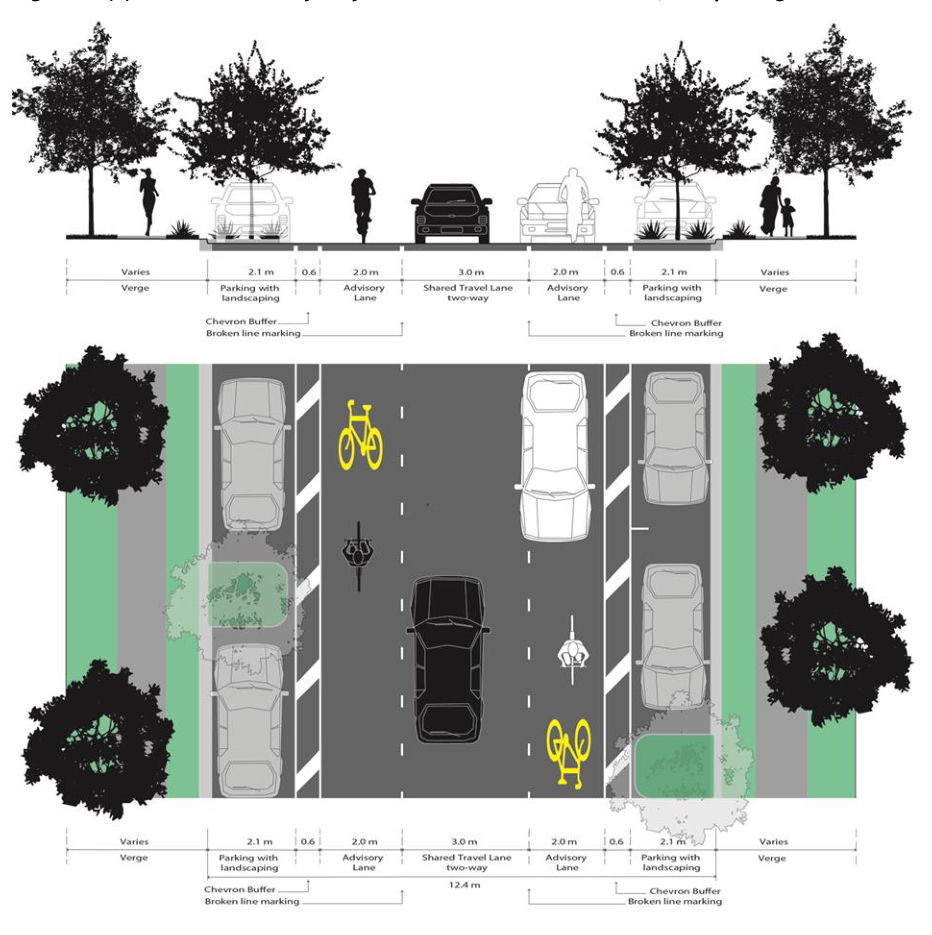
- 2.0 m ABLs marked with dashed lane lines and yellow bicycle symbol. The bicycle symbol should be marked in accordance with TRUM Volume 1, Part 10, Section 6.5.1 Bicycle Awareness Zones. The placement of the yellow bicycle symbol should locate the bicycle rider away from the door zone. Green surface treatment may be used to highlight the complete length of the ABL, but is not mandatory. Hazardous locations must be highlighted with green surface treatment in accordance with Austroads Guide to Road Design: Part 3. An example of appropriate green surface treatment is shown in Appendix A.
- Minimum 0.5 m chevron buffers with audible tactile line marking every 5 m must be marked beside parking bays to highlight the 'door zone'
Central shared traffic lane widths could vary between 3.0 – 5.5 m. Table 5.1 illustrates the issues to be considered when deciding on minimum shared traffic lane widths
| Two way travel lane widths | Considerations | |
|---|---|---|
| Minimum width | 3.0 m | On low volume streets where oncoming vehicle occurrence is likely to be lower. Requires vehicle encroachment into the ABL when vehicles travelling in opposite directions meet |
| Preferred width | 4.3-4.5 m | Two motor vehicles are able to meet each other within the centre lane at very low speeds. In practice, vehicles will encroach into ABLs |
| Maximum width | 4.9 m | Permits two motor vehicles to meet each other at slow speeds without encroaching into the ABLs |
| Absolute maximum width | 5.5 m | This is equivalent to two narrow travel lanes and regular encroachment into the ABL may not be necessary |
Importantly, a dividing road centre line must not be marked. A central shared traffic lane encourages lower vehicle speed, and the preferred vehicle driver behaviour of waiting to overtake bicycle riders after an oncoming vehicle has passed, instead of squeezing through too close to the bicycle rider.
- Dashed lane lines result in vehicle lateral tracking towards the centre of the road, away from bicycle riders. Dashed lane lines provide clear operating space for bicycle riders, which can be shared by vehicles. Dashed lane line is 1 m long, with 3 m long gap and is 150 mm wide (same as a continuity line).
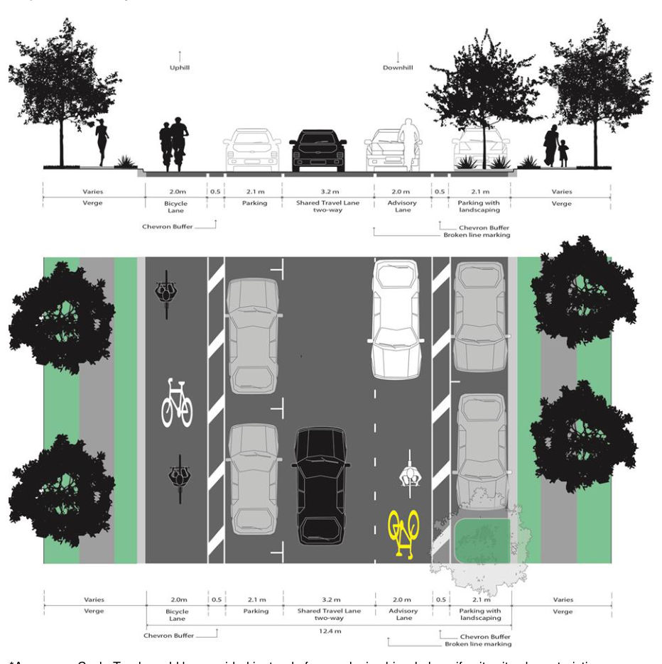
- There are variations for uphill or downhill grades >2%, see Figure 5.1(e).
- Easy to retrofit, can work with existing car parking or on roads with no car parking. Parking can be located one side or both sides. If parking is marked on one side where >2% gradient, locate parking on uphill side to allow ABL to be located adjacent to kerb and away for the door zone on the downhill side. Landscaping can also be provided in line with car parking to frame and increase predictability. Car parking could be indented into the verge area or landscaping provided in car parking lane to frame/indent cars.
- Treat the ABL at T-intersections, curves, crests and at slow points to provide priority and visibility for cyclists at these potentially hazardous locations in accordance with Appendix A. These should also be considered in the context of area wide LATM measures and in accordance with Austroads Guide to Traffic Management Part 8: LATM.
The following figures illustrate the cross section options available for ABLs. Considerations of preferred facility type against road function, traffic volume and cross section width can be found in Figure 4.2.
*A one way Cycle Track could be provided instead of an exclusive bicycle lane if suits site characteristics
5.2Education and awareness#
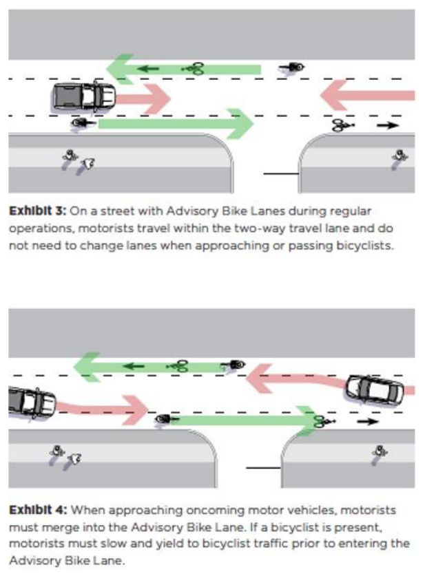
ABLs will be unfamiliar cycle facility treatments in Queensland, and therefore information on how all users behave on streets with these treatments may need to be provided until the facility type is more commonplace. Education and awareness campaigns should be considered before and during implementation.
Information on how the lanes operate and how users should behave could be promoted at the site and as part of various awareness campaigns.
Examples of useful information to guide users on ABLs are found in Figures 5.2(a) and (b) following.
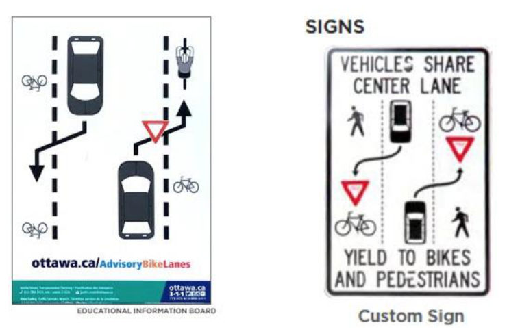
An example of a good educational video produced for the City of Ottawa is provided at the following link - https://www.youtube.com/watch?v=0zdDIvKXMxY&feature=youtu.be
5.3Case studies#
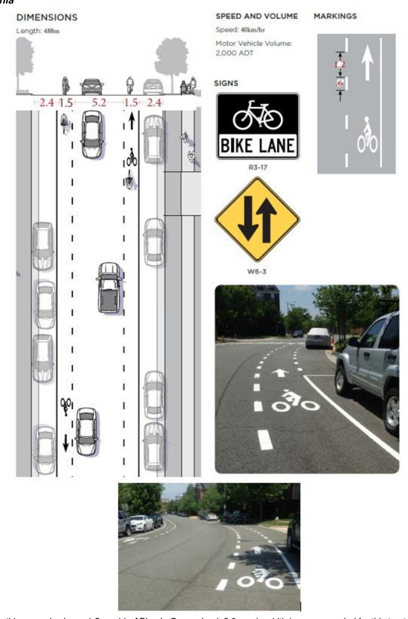
5.3.1Potomac Greens Drive, Alexandria, Virginia#
Potomac Greens Drive is one of two roads providing access to a medium density residential neighbourhood. It experiences no through traffic due to the neighbourhood being bordered by two railway lines and a major arterial road. The speed limit is posted at 40 km/hr with a vehicle volume of 2000 vpd. The road experienced demand by cyclists due to a bike share station located near the entry to the neighbourhood. An exclusive bicycle lane could not be achieved without removing a car parking lane, which was not an option as it received heavy use.
Residents felt that the road in its previously unmarked state encouraged speeding and recommended speed bumps be installed. After a traffic survey performed by the city showed inconclusive evidence of speeding, ABLs were installed as an alternate traffic calming solution. The City held two meetings to educate the community and received positive and negative responses from residents. After the installation of the ABLs, the City further distributed explanatory flyers and created an information web site for the community and little response was recorded from the residents.
The installation of the ABLs is working as intended and currently being evaluated.
5.3.2East 14th Street, Minneapolis, Minnesota#
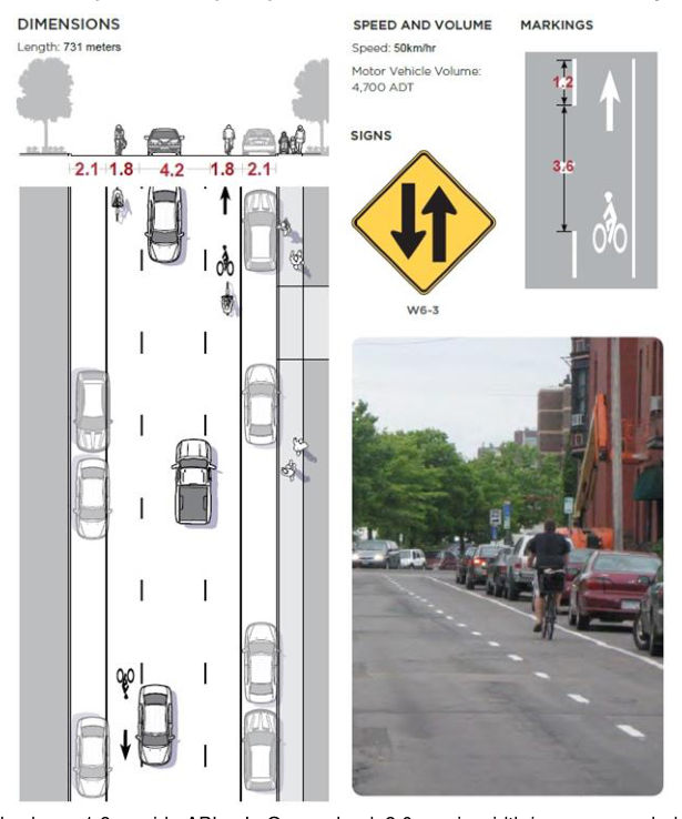
East 14th Street has a mix of commercial and dense residential uses along its length and is located along the edge of a downtown area. It is not a through traffic route but has important destinations along it such as hospitals and grocery stores, and hence has higher traffic volumes recorded at 4700 vpd. The recorded speed limit is 50 km/hr.
The street connects three north / south exclusive bicycle lanes and therefore an important part of the cycle network. There was not enough room to provide exclusive bicycle lanes and the car parking located on both sides of the road experienced high demands.
The city consulted with neighbourhood groups and other organisations during design and after installation published video and educational materials. Public concern declined significantly one month after installation.
The facility is operating as intended. There was some reported confusion about the narrow lane and lack of marked centre lane but the confusion was not reflected in reported crashes or observed user behaviour. The city believes the context provided by parking lanes on both sides of the road combined with narrow widths provided appropriate cues for two way operation and the need to negotiate space between users.