4.4Horizontal alignment#
Horizontal alignment requirements can place significant constraints on the potential road alignment for temporary roads. This can have a significant impact on both the costs of the construction of the temporary road and on the constructability of the works in constrained sites.
The following guidance relating to horizontal alignment may be applicable to temporary road alignments.
4.4.1National / International guidance – literature review#
In considering potential design exception criteria for sight distance for temporary roads documented guidance has been reviewed and considered from Transport and Main Roads (existing guidelines and the adopted Austroads Guide to Road Design), Main Roads WA and the USA.
4.4.1.1Queensland#
The department’s Guidelines for Road Design on Brownfield Sites (2013) identifies that specific design elements that are considered and which appear relevant to the application on temporary roads include: horizontal alignment. However no particular parameters are discussed.
4.4.1.2Australia – National guidance (AGRD)#
AGRD03 notes that “the horizontal curvature should be used to control operating speeds through a transition section, since horizontal curvature has the greatest effect on operating speed”. No relaxations to permanent road design parameters are discussed for application at temporary roads.
Section 7.8 of AGRD03 discusses that adverse crossfall may also be used on temporary roads and side-tracks. In these cases, superelevation and side friction factors may not align with NDD design practice.
4.4.1.3Western Australia#
Main Roads WA design guidance identifies that “temporary alignments in place for up to twelve months that cannot meet the Main Roads Horizontal Curve Tables criteria shall apply superelevation at a rate based on the Main Roads Supplement to Austroads GRD Part 3: Geometric Design using the desirable friction factor but with no distribution of e or f ie:- E = V2/(127R) - fdes”.
It further identifies parameters related to:
- Superelevation - A minimum superelevation and/or crossfall of 2% is required to cater for drainage on sealed surfaces.
- Adverse crossfall = If adverse crossfall is to be used then Fdes shall be limited to 50% of Fdes, as recommended by the Main Roads Supplement to Austroads GRD Part 3: Geometric Design.
4.4.1.4USA#
The road alignment design parameters that are discussed in the context of temporary road design include:
- Superelevation and side friction – these parameters are typically chosen on the basis of driver comfort criteria. For temporary roadways, parameters which are based on typical vehicle – pavement interactions can be used which approach maximums, particularly for side friction. The use of adverse crossfall may be appropriate in these circumstances to reduce the need to introduce superelevation.
- Horizontal Alignment and Superelevation – as cost and impacts of a side track relate to the length of the alignment between tie-in points on the permanent roadway, it is preferred to use the smallest curve radii that satisfy all design considerations.
4.4.2Case Examples#
Case examples from projects in Queensland included design exception on the basis that:
- The horizontal alignment for a temporary road at a site was restricted due to the site constraints and a diversion of the road alignment was implemented with no separation between reverse curves.
- On a curve with adverse crossfall, curve radii of R400 was adopted which complied with the desirable maximum side friction for cars but not for trucks. Additional VMS were applied to advise truck drivers of the road geometry and appropriate warning speeds.
4.4.3Design opportunities – horizontal alignment#
The following horizontal alignment elements are considered relevant to the consideration of temporary roadways:
- Types of Horizontal curves:
- Compound curves, broken back curves and reverse curves while undesirable but can be accepted in constrained situations and are all likely to be more common for temporary alignments at roadworks. The key risk associated with these horizontal design features is an increased risk of drivers misjudging the path to follow to negotiate the curves.
- The design of these curves should continue to be undertaken in accordance with the guidance in the RPDM Part 3 and AGRD03 and hence does not represent a Design Exception.
- Side friction and minimum curve size:
- The factors associated with establishing the minimum curve size include the pavement superelevation (e) and the side friction factor (f). The desirable and absolute maximum side friction factors are presented for cars and trucks in AGRD3 Table 7.5. Consider use of the absolute maximum side friction factor (f) for horizontal curves for temporary alignments. The application of absolute maximum side friction and inclusion of adverse crossfall is considered to be an EDD design parameter. However care needs to be taken to ensure that use of fmax considers the changes in friction between horizontal alignment features and is not applied on an isolated curve. However, as identified in the case study examples previously applied in Queensland, a design exception has previously been approved on the basis of meeting side friction requirements for cars but not for trucks.
- Curves with adverse crossfall:
- − AGRD03 states that adverse crossfall on curves should normally be avoided except on curves of very large radius relative to the operating speed that can be regarded as straights. Table 7.12 of AGRD03 gives minimum radius curves for various operating speeds for which adverse crossfall may be considered. In constrained temporary roadworks sites it is considered more likely that difficulties will arise in creating the necessary superelevation for curves, particularly for reverse curves at the start and end transition areas between the temporary alignment and the permanent alignment.
- − While not desirable, the design of these curves with adverse crossfall should continue to be undertaken in accordance with the guidance in the RPDM Part 3 and AGRD03 and hence does not represent a Design Exception.
4.4.4Mitigating measures – horizontal alignment#
In situations where side friction requirements may not be met for heavy vehicles, the primary risks are associated with these vehicles either not negotiating the curves, or potentially overturning. The application of and design exception relating to side friction requirements for heavy vehicles would require consideration of the following potential mitigating factors:
- Speed limit compliance – to ensure that the majority of traffic is travelling at or below the posted speed limit.
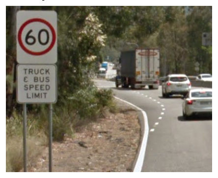
- Speed limit compliance for heavy vehicles. The QLD Road Rules Regulation 104 (reproduced below – in part) appears to allow the use of a “No Trucks” sign to apply to only some lanes on a road as per subsection (5). The relevant parts of the clause are highlighted.
QLD Road Rules Regulation 317 (reproduced below in part) define how the use of traffic control devices can apply to a particular vehicle.
Regulation 317Information on or with traffic control devices#
- (1)A traffic control device may, by the use of words, figures, symbols or anything else indicate any of the following—
- (a)the times, days or circumstances when it applies or does not apply;
- (b)the lengths of road or areas where it applies or does not apply;
- (c)the persons to whom it applies or does not apply;
- (d)the vehicles to which it applies or does not apply;
- (e)other information
An example of the application of such a sign from Great Western Highway in the NSW Blue Mountains is shown at Figure 4.4.4.
- Additional warning signage to alert heavy vehicle drivers to the presence of the curves and the appropriate warning speed.
- Crash records and near incidents – should be assessed regularly to establish if a lower speed limit needs to be implemented on a permanent basis with additional design measures introduced to address vehicle speeds should crash records be unacceptable.