
5Sign supports#
5.1Post size and selection#
A graphical method of post selection is used in this Guide, similar in format to that used in AS1742.2-2009. Each geographic wind region is catered for with a separate table for clarity and ease of use. The post size is chosen directly from the table for a given sign size, height and number of posts. An option is given for either CHS or RHS posts.
5.2Single post signs#
5.2.1Signs up to 950mm wide#
Standard regulatory, parking, warning and guide signs up to 950mm wide are generally erected without panel stiffeners and are supported on a single post. Sign panels greater than 700mm wide and 1000mm deep are sometimes prone to twist and panel deformation. For this reason, consideration should be given to stiffening with Type 1 panel stiffeners.
Boltholes should be provided in sign panels up to 950mm wide and 1000mm deep. The suggested rules for boltholes are listed in Table 5.2.1(a).
| Sign width (mm) | Sign height (mm) | Number and spacing of holes (mm) |
|---|---|---|
| < 950 | < 250 | 1 |
| < 950 | < 350 | 2@200 |
| < 950 | < 550 | 2@300 |
| < 950 | < 800 | 2@500 |
| < 950 | < 1000 | 2@750 |
This assumes even vertical hole spacings of 200, 300, 500 and 750mm.
It is recommended that flattened posts not be used. However, if refitting existing signs to the existing flattened posts than the spacings in Table 5.2.1(b) must be specified when ordering.
| Sign width (mm) | Sign height (mm) | Number and spacing of holes (mm) |
|---|---|---|
| < 950 | < 250 | 1 |
| < 950 | < 350 | 2@205 |
| < 950 | < 550 | 2@310 |
| < 950 | < 800 | 2@510 |
| < 950 | < 1000 | 2@735 |
5.2.2Sign posts#
For standard regulatory, parking, warning and guide signs refer to Standard Drawing SD1368 Traffic sign – Single traffic sign support for typical brackets used. Flattened posts with corresponding holes are no longer in general use in most districts and brackets are recommended instead.
For signs less than 1 m² in area, the post size is generally 50 DN x 3.2mm CHS. Refer to Appendix B for determination of post sizes suitable for larger signs or heights.
Single posts will generally be CHS, although RHS should be considered for larger signs to increase resistance to twisting.
5.2.3Fittings#
Standard Drawing SD1369 Traffic sign – Details of sign stiffening extrusion shows several basic types of fittings referred to as Fittings B1, B2, B3, and B4. These are only for 50 DN posts and are a basic standard only. Alternative brackets and variations on these themes are readily available and in most cases equally effective. The user will have to consider their individual requirements before selecting a bracket for a particular purpose. Brackets for 65 DN are available but will not normally be required.
Fittings B1 and B2 are generally used for the erection of single sided standard signs. Fitting B3 is used to erect back-to-back standard signs on a common post.
Fitting B4, wing saddle brackets, are used for single-sided signs. These brackets provide resistance to movement but require site drilling of the post.
5.2.4Signs over 950mm wide#
For sign faces over 950mm wide, the use of multiple support posts is generally recommended to avoid panel twist due to vandalism or wind buffeting. For situations where a two-post support is not possible (for example, narrow urban median strips), a single post may be used with panel stiffeners fixed in accordance with Standard Drawing SD1368 Traffic sign – Single traffic sign support for signs up to 1800mm wide. Refer to Appendix B for the design procedure.
If breakaway posts are required (refer to Section 5.3.4), the slip base detail given on Standard Drawing SD1368 Traffic sign – Single traffic sign support is recommended for single post signs subject to impact from any direction. The fuse plate detail is unnecessary and should not be used with single post signs.
Brackets are available that resist twisting, such as the Signfix Type 5 Bracket.
5.2.5Posts in sleeves#
There are certain situations where it is advisable to install the post into a sleeve inserted into the footing, such as:
- 1)where a sign is located on an urban median strip where it may be struck frequently, or
- 2)where it may need to be removed occasionally, to accommodate the swept path of over-dimensioned vehicles when turning.
This arrangement is only appropriate for small posts up to 50 DN.
Details of a typical sleeve assembly are presented in Standard Drawing SD1368 Traffic sign – Single traffic sign support. An alternative assembly called the ‘loc Socket’ is also shown on Standard Drawing SD1368 Traffic sign – Single traffic sign support. This is a commercial product and variations on the basic theme are just as effective.
5.3Multiple support signs#
For sign widths greater than 950mm, panel stiffener rails are attached to the sign face and connected to two or more supports (refer to Section 5.2.4 for discussion of the single post alternative).
The term support here refers to a CHS or RHS post. This Guide may be used for signs up to 8m in height and up to 8m in width, with a maximum area of 40m².
5.3.1Panel stiffener rails#
Two panel stiffener sections are used in fabrication of signs greater than 950mm in width, Type 1 and Type 2A. Refer to Standard Drawing SD1369 Traffic sign – Details of sign stiffening extrusion for specification of aluminium extrusions.
Stiffener type and number is derived from Appendix B, tables B.1, B.2 and B.3 for a particular sign width, height and location. Table B.1 presents three options for choice of stiffener type and number of supports:
Option 1: The most economical option using a minimum number of supports spaced at the standard spacing of 60% and 35% of sign width for two and three support signs respectively.
Option 2: This alternative arrangement may be adopted where an additional support is used to achieve ‘frangible’ section sizes. Note the limitations on support spacing to achieve a satisfactory ‘frangible’ solution. This option maintains the standard support spacings to derive the maximum sign width; however, reduced post spacing may be used as long as the maximum stiffener overhang is not exceeded.
Option 3: An option for signs requiring two widely spaced supports, for example, straddling a footpath, where the minimum overhang is 10% of sign width.
For sign widths less than the tabulated limits, the support spacing may be reduced below the standard spacing ratio to suit the site conditions; however, the maximum stiffener overhang specified in Table B.2 must not be exceeded.
Additional posts may be used to achieve ‘frangible’ section sizes if required; however, increasing the number of posts is not a valid method for resultant post spacing less than 1.5m, due to the increased likelihood of collision with two posts
Deviation from the specified stiffener / support arrangements will require calculation of width limits in accordance with the appropriate formulae.
General constraints on stiffener arrangements are as follows:
- 500mm maximum stiffener spacing, and
- 150mm maximum panel overhang between stiffeners and top and bottom of sign.
For large signs erected using modular panels, refer to Section 4.
5.3.2Sign supports#
Tubular steel posts are used to support the stiffened sign panel, either Circular Hollow Section (CHS) or Rectangular Hollow Section (RHS).
The number of supports and options for support type (RHS / CHS) are determined from the procedure in Appendix B. The selection of support type is influenced by the following considerations:
CHS has generally been the preferred post type due to:
- availability as pregalvanised (300g/ms), which saves the cost and inconvenience of hot dip galvanising RHS
- less wastage in fabrication due to 6.5m length stock sizes compared to 8m for RHS
- less tolerance on length required due to ease of pipe cutting and capping on site
- less tolerance on alignment with sign face required
- availability of fittings, and
- more easily realigned if bent over by wind or vehicle impact.
RHS posts are significantly more efficient than CHS as structural sections, particularly with the benefit of availability as Grade C350/450.
In regions of Mild and Moderate Atmospheric Classification¹, advantage may be taken of pregalvanised (100g/ms) RHS which has recently become available for sizes up to 125 x 75 and is half the cost of equivalent capacity galvanised CHS. This cost saving should be considered against the erection advantages of CHS.
In urban areas, the likelihood of corrosion from dog urine should also be considered. Although urine will attack all levels of galvanising, the heavier hot dip galvanised coating will give greater protection to the steel.
Posts for signs located in ‘high risk’ areas which are ‘non-frangible’ (refer Section 5.3.4), must be hot dip galvanised after fabrication of slip baseplate and fuse plate hinge details as specified in Standard Drawing SD1365 Traffic Sign – Traffic sign support breakaway post details (two or more supports).
The cost and convenience benefits inherent in having CHS pre-galvanised are therefore removed and the cost savings of RHS, as discussed previously, should be considered.
Posts in sleeves (refer Section 5.2.5) must be CHS posts.
5.3.3Alternative post section sizes#
Table B.5 presents some alternative post section sizes for CHS posts to those called up in Figures B.2–B.13. The preferred sizes, based on structural efficiency and availability, are highlighted in Table B.5.
5.3.4Breakaway supports#
The function of breakaway supports is to support the sign under normal wind load conditions, yet fail in a relatively safe manner when struck by a vehicle.
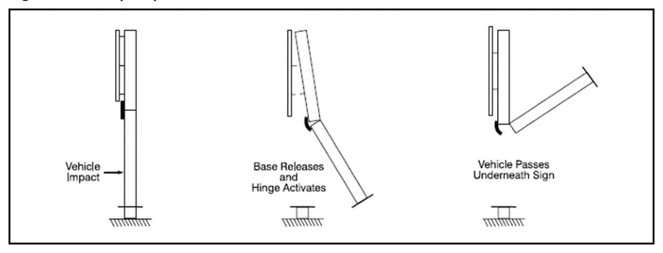
Breakaway supports are fabricated using RHS or CHS steel tube with both a slip baseplate and a fuse plate hinge (except for single post signs). Failure occurs when the vehicle impact force overcomes the frictional force between the baseplate and tension tearing of the fuseplate weld. Breakaway support details are designed to accommodate impact from both traffic directions, to cater for use in median strip and gore areas.
The slip base and fuse plate details are not required for small posts, which are considered to be ‘frangible’ in collisions. Refer to Table 5.3.4.
| Likely collision speed (km/h) | Post size Diameter nominal (mm) | Post size Outside diameter (mm) |
|---|---|---|
| < 60 | 100 | 114.3 |
| 60 to 80 | 80 | 88.9 |
| > 80 | 65 | 76.1 |
Galvanised steel pipe posts up to 65 DN will rarely be found to cause injury to the occupants of cars or heavier vehicles which collide with them. The same applies to low-speed urban type conditions involving steel pipe up to approximately 100 DN (RHS 75 x 50). For RHS, 75 x 50 posts may be considered as ‘frangible’.
Consideration should be given to the use of an additional post that may reduce the required post size to within the ‘frangible’ limits. Increasing the number of posts is not a valid method for resultant post spacing less than 1.5m, due to the increased likelihood of collision with two posts.
To maximise road safety and minimise cost, the intention should always be to locate signs in ‘low risk’ regions where breakaway posts are not required.
‘Low risk’ regions are:
- outside the Clear Zone defined in Section 3
- behind a guard rail or other barrier device, or
- at the bottom of a steep embankment or top of a steep cutting.
‘High risk’ regions are those within the Clear Zone defined in Section 4 which are not protected by a barrier device or steep slope.
Breakaway posts should be avoided where secondary accidents involving the impacting vehicle or dislodged pole and sign are significant. This is particularly relevant in urban areas where pedestrians may be struck by falling pieces.
To achieve satisfactory performance of the breakaway supports, the following criteria should be met:
- The clearance of the sign above the ground should be a minimum of 2.1m to avoid penetration of an impacting vehicle windscreen.
- Proper functioning of the slip base depends on control of clamping pressure between the base plates produced by bolt tensioning. It is important for the specified bolt torque to be adhered to. The drawings specify shop assembly of slip bases, to minimise the inaccuracies of torque controlled bolt tensioning. Pre-assembled slip bases will also enable supports to be plumbed prior to pouring concrete footings.
- For CHS / RHS posts, the fuse plate hinges have been designed to resist 45% of the post moment capacity. Signs with panel height (‘B’) greater than 165% of the clearance (‘H’) between the ground and sign produce a bending moment which exceeds the fuse plate hinge capacity. For these signs the post size should be increased to the next section size. The allowable panel height is then twice the clearance.
Breakaway support details are presented in Standard Drawing SD1365 Traffic sign – Traffic sign support breakaway post details (two or more supports) for CHS / RHS posts
5.4Fittings#
5.4.1Connection straps#
Stiffener rails are generally fixed to supports with circular or rectangular connection straps. Galvanised steel connection straps for CHS supports (including trusses) and RHS posts are detailed on Standard Drawing SD1364 Traffic sign – Connection strap and erection cleat details.
5.4.2Erection cleats#
To assist the erection of RHS posts, cleats may be welded to the posts to support the top stiffener rail. Slotted cleats allow the sign to be levelled, as connection straps are fitted to the remaining stiffener rails. Erection cleats are detailed on Standard Drawing SD1364 Traffic sign – Connection strap and erection cleat details.
5.5Proprietary sign supports#
Refer to Traffic and Road Use Management manual Volume 1 Part 10 Section 4.5.3-1.
5.6Sight boards and other signs at T-intersections#
Signs installed parallel to the roadway that include sign stiffeners present a spearing risk to vehicles that impact them end on. Transport and Main Roads has developed new installation guidelines to ensure that signs do not spear through vehicle windscreens when impacted. These revised installation guidelines are given in Standard Drawing SD1452 Traffic sign – Hazard marker installation details. The Standard Drawing is to be read in conjunction with Appendix E: Design of Sight boards and other signs at T-intersections.