20.6Installation#
20.6.1General#
Steel beam guardrail shall be installed in the locations shown in the design documentation and in accordance with the details shown on Standard Drawings 1467, 1470, 1474, 1475, 1476, 1477, 1478, 1479 and 1482.
Where installation of posts cannot be placed in accordance with the design drawings, it may be necessary to drill additional holes to facilitate installation. In this instance, additional holes shall be drilled either by a magnetic or pneumatic drill and treated in accordance with AS/NZS 4680. No flame cutting is permitted.
All bolts and nuts shall be securely tightened after installation. Washers shall not be used except where shown on the drawings.
Bolts for slip base plates shall be fastened to the torque specified on Standard Drawing 1476.
Any damage to guardrail components which occurs during the Contract shall be repaired to a finish complying with the requirements of this Technical Specification.
20.6.2Posts for Longitudinal Barrier (excluding public domain end treatments)#
Steel posts may be driven or installed by the excavation and backfilling of a post hole. Posts shall not be driven into any asphalt layer or into concrete or into rock or into any pavement layer constructed in accordance with the requirements of Technical Specification MRTS07A Insitu Stabilised Subgrades using Quicklime or Hydrated Lime, MRTS07B Insitu Stabilised Pavements using Cement or Cementitious Blends, MRTS07C Insitu Stabilised Pavements using Foamed Bitumen, MRTS08 Plant-Mixed Heavily Bound (Cemented) Pavements, MRTS09 Plant-Mixed Foamed Bitumen Stabilised Pavements or MRTS10 Plant-Mixed Lightly Bound Pavements.
Where a post is to be installed into an asphalt layer or into concrete or into rock or into any pavement layer constructed in accordance with the requirements of Technical Specification MRTS07A Insitu Stabilised Subgrades using Quicklime or Hydrated Lime, MRTS07B Insitu Stabilised Pavements using Cement or Cementitious Blends, MRTS07C Insitu Stabilised Pavements using Foamed Bitumen, MRTS08 Plant-Mixed Heavily Bound (Cemented) Pavements, MRTS09 Plant-Mixed Foamed Bitumen Stabilised Pavements or MRTS10 Plant-Mixed Lightly Bound Pavements the following procedure shall be used:
- a hole of at least 400 mm diameter shall be excavated or bored to within 300 mm of the bottom of the post or to not less than the underside of the constraining material as described above whichever is the shallowest
- the hole shall be located so that the intended location of the post is aligned either centrally in the hole or closer to the side of the hole closest to the traffic lane from which most errant vehicles will originate
- the post shall be driven to the correct height
- the hole shall be backfilled around and within the open section of the post with clean, well-graded sand compacted so that it does not settle or arch, nor do voids form within the backfill, and
- the top 40 mm shall be completed with a sand-cement mortar.
During the driving of any post, an appropriate packer shall be used to protect the head of the post from damage and no damage shall occur to the post or to any protective coating. Any coating that is damaged during driving shall be repaired in accordance with AS/NZS 4680. The recommended repair for damaged galvanising is to apply two coats of inorganic zinc primer applied by brush.
The method of installation shall be recorded in the quality documentation.
20.6.3Posts for public domain end treatments#
The in-ground part of each of the six slip-base posts comprising a Terminal Type 1 end treatment as depicted on Standard Drawing 1474 (and others) may be driven or installed in a concrete footing. The concrete footing for each slip-base post shall be grade N25/20 concrete of a minimum diameter of 450 mm and of full depth to the bottom of the installed post. Where slip-base posts one and two are installed in a concrete footing, the soil plates may be omitted from these two posts.
Where Terminal Type 1 end treatments are to be installed in bound (i.e. AC or CTB) pavements it may be convenient (to the installer) to drive the slip-base footings. If so, providing that the total bound pavement depth where the post is being installed is not less than 330 mm thick measured from the surface, the soil plates may be omitted from posts one and two. It shall be incumbent upon the contractor / installer to demonstrate that driving posts through the bound pavement does not cause damage to the post which will be detrimental to the performance or the durability of the post. The contractor / installer shall make good any damage to the pavement around the base of the post caused by the driving process.
Otherwise, the installation shall be in accordance with Standard Drawing 1474 and the soil plate shall be installed. Other slip base posts shall be erected strictly in accordance with the details shown on Standard Drawing 1476.
The proposed method of installation of guardrail posts shall be included in the Construction Procedures required under the provisions of Clause 6 of MRTS50 Specific Quality System Requirements.
The soil plate on the Type 2 (departure) terminal as depicted on Standard Drawing 1474 (and others) may not be omitted.
20.6.4Anchor cables#
Anchor cables shall be erected strictly in accordance with the details shown on Standard Drawings 1474, 1476 and 1477. The nuts at both ends of each cable shall be tightened to a torque of 50 Nm.
The test certificate shall be traced back to the individual cables supplied to the project, via an identification tag.
20.6.5Delineator spacing#
Delineators on public domain steel beam road safety barriers shall be mounted at the spacings prescribed in Part 2 of the MUTCD. The colour of delineators shall be in accordance with the requirements of the MUTCD.
Delineators shall conform with the requirements of Clause 10.2.4 and shall be attached to the barrier in accordance with the detail on Standard Drawing 1478.
The fixing bracket shall be attached to the top of the concrete road safety barrier with one 10 mm diameter masonry anchor with a minimum of 30 mm into concrete.
20.6.6Tolerances#
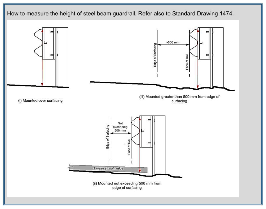
Steel beam guardrail shall be installed to the line and level shown in the design documentation. The tolerance on verticality of post shall be +/-15 mm measured at the top of the post. The tolerance on post height shall be +/-10 mm. The tolerance on rail height shall be +/-10 mm. Height to the top of rail shall be measured at midspan between posts:
- Where the face of steel beam guardrail is located above surfaced pavement, the height shall be measured from the pavement surface to the top of the rail.
- Where the face of steel beam guardrail is located not more than 500 mm beyond the edge of surfacing, a 3 m straight edge shall be lain perpendicular to the alignment of the road centreline to extrapolate the cross slope to meet a point plumb vertically below the back face of the rail. The height shall be measured vertically from this point to the top of the rail, and
- Where the face of steel beam guardrail is located beyond 500 mm from the edge of surfacing, the height shall be measured vertically from the ground surface to the top of the rail.
During installation, all elements of the steel beam guardrail shall fit together without the need to enlarge any holes, drill additional holes or modify any component.
20.6.7Acceptance of installation#
Final acceptance of the guardrail installation shall not occur until the Administrator has reviewed that the installation has been installed as per the design documentation and in accordance with the details shown on Standard Drawings and released the Hold Point. Hold Point 10
Guardrail components not installed in accordance with the requirements of the design documentation and in accordance with the details shown on Standard Drawings shall be removed and installed correctly.
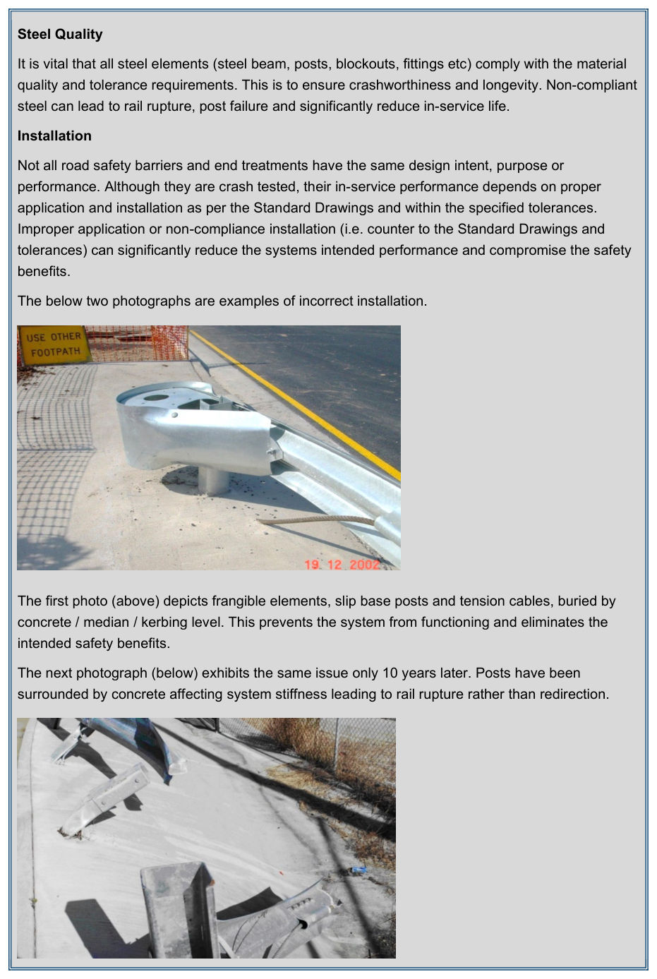
| Steel Quality |
|---|
| It is vital that all steel elements (steel beam, posts, blockouts, fittings etc) comply with the material quality and tolerance requirements. This is to ensure crashworthiness and longevity. Non-compliant steel can lead to rail rupture, post failure and significantly reduce in-service life. |
| Installation |
| Not all road safety barriers and end treatments have the same design intent, purpose or performance. Although they are crash tested, their in-service performance depends on proper application and installation as per the Standard Drawings and within the specified tolerances. Improper application or non-compliance installation (i.e. counter to the Standard Drawings and tolerances) can significantly reduce the systems intended performance and compromise the safety benefits. |
| The below two photographs are examples of incorrect installation. |
| The first photo (above) depicts frangible elements, slip base posts and tension cables, buried by concrete / median / kerbing level. This prevents the system from functioning and eliminates the intended safety benefits. |
| The next photograph (below) exhibits the same issue only 10 years later. Posts have been surrounded by concrete affecting system stiffness leading to rail rupture rather than redirection. |
Table in words
- Steel Quality: It is vital that all steel elements (steel beam, posts, blockouts, fittings etc) comply with the material quality and tolerance requirements.
- Steel Quality: This is to ensure crashworthiness and longevity.
- Steel Quality: Non-compliant steel can lead to rail rupture, post failure and significantly reduce in-service life.
- Installation: Not all road safety barriers and end treatments have the same design intent, purpose or performance.
- Installation: Although they are crash tested, their in-service performance depends on proper application and installation as per the Standard Drawings and within the specified tolerances.
- Installation: Improper application or non-compliance installation (i.e. counter to the Standard Drawings and tolerances) can significantly reduce the systems intended performance and compromise the safety benefits.
- Installation: The below two photographs are examples of incorrect installation.
- Installation: The first photo (above) depicts frangible elements, slip base posts and tension cables, buried by concrete / median / kerbing level.
- Installation: This prevents the system from functioning and eliminates the intended safety benefits.
- Installation: The next photograph (below) exhibits the same issue only 10 years later.
- Installation: Posts have been surrounded by concrete affecting system stiffness leading to rail rupture rather than redirection.