4.3Estimated queue length#
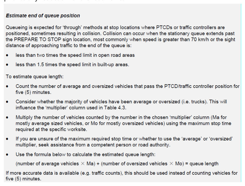
For the purpose of estimating the end-of-queue position only, the term 'oversized vehicles' also includes 'heavy vehicles'.
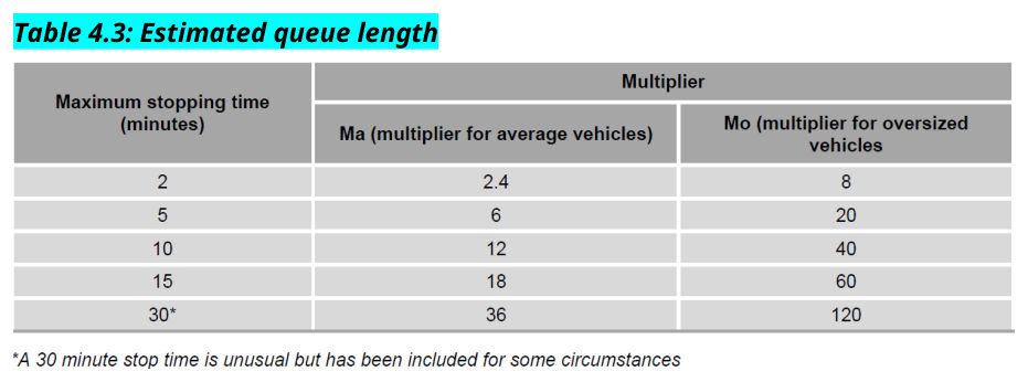
When estimating the queue length, Table 4.3 uses an average vehicle length of 6 m and an average heavy vehicle length of 20 m for a five minute stopping time (based on the five minute traffic count) and then adjusts the multipliers for other stopping time values.
Where very long vehicles are expected (for example outback and mining routes or routes where most vehicles are towing), then to ensure estimated queue lengths are as accurate as possible, an average length per vehicle that matches the actual traffic mix expected at that location should be used.
The estimated queue length must be at least a minimum of one average vehicle plus one heavy vehicle (of a length which may be applicable to the site). Part lengths of vehicles must be rounded up when estimating queue lengths.
To calculate the 'maximum stopping time' value used in Table 4.3 for each approach, the Traffic Management Designer must estimate the likely duration of time that queued traffic will be stopped at a traffic control station. Calculating the maximum stopping time needs to include the total time from when the traffic controller stops traffic, through until the same traffic controller releases traffic for the next cycle from that approach.
This would typically include the following considerations:
- the time taken for the traffic queue from one approach to pass the traffic control station and travel the length of the closure
- the time for the queue at the other end of the site to leave that traffic control station and also travel the length of the closure (this may commence at the same time as the other queue or following the completion of the other queues travel if shuttle flow is in operation)
- if traffic queues are held for a period (with no traffic traveling through or past the site), then this hold time will also need to be included
- a factor of safety may also be allowed for vehicles travelling the closure below the signed speed limit, and
- if more than two traffic control stations (one each end) are in operation, depending on the operating characteristics of the roadworks site, the time for each queue to be released and travel through the roadworks site may need to be considered and included.
The 'maximum stopping time' value will be used in Table 4.3 to determine the multipliers to be used with the number and type of vehicle (average or heavy) from the five minute count or calculation.
4.4(a)Maximum spacing for repeater PREPARE TO STOP signs#
| Speed (km/h)* | Distance (m) |
|---|---|
| ≤55 | 60 |
| ≥56 | 180 |
* The 'Speed' value to be used for the maximum spacing for repeater PREPARE TO STOP signs is the actual posted speed (temporary or permanent) which applies (this will generally be 60 km/h but may be less) where the repeater spacing is required. If the speed limit changes within a repeater spacing, use the spacing for the lower speed limit.
4.4(b)Minimum distance from ROADWORK AHEAD or variable message sign to primary PREPARE TO STOP sign#
| Speed (km/h)^ | Distance (m) |
|---|---|
| ≤55 | 30 |
| ≥56–65 | 90 |
| ≥66–75 | 140 |
| ≥76–85 | 240 |
| ≥86 | Four times the speed (km/h) |
^The 'Speed' value to be used for the minimum distance from the ROADWORK AHEAD or variable message sign to the primary PREPARE TO STOP sign is the actual permanent posted speed of the road prior to any reduction for the roadworks.
An estimated end-of-queue position is to be determined for the approach to each traffic control station and is to be based on the maximum expected traffic flow on that approach during the time traffic control will be in operation.
The count or estimate of the number of average and heavy vehicles during a five-minute period at a site may be completed using the following in order of preference:
- 1.Actual five-minute count of vehicles during the peak time the site will be occupied. This five-minute count is based on the vehicles approaching the selected traffic control station from the approach to be controlled by that station (not a sum of both directions of traffic). Consideration of peak traffic flow direction may be needed.
- 2.If a five-minute count is not possible, use annual average daily traffic (AADT) values with hourly breakdowns and percentage heavy vehicle data. To estimate the five-minute count, select the peak hourly period during the time the site will be occupied and divide by 12 to get an estimated five-minute value. Divide this by two if the AADT is for a two-way road. Use the percentage heavy vehicles information with this value to estimate the number of heavy vehicles for this five-minute period.
- 3.If a five-minute count is not possible, and AADT values with hourly breakdowns are not available, use AADT values and percentage heavy vehicle data. To estimate the five-minute count, firstly divide the AADT by a factor of 10 (to get an estimated hourly count) and then divide this by 12 to get an estimated five-minute value. Divide this by two if the AADT is for a two-way road. Use the percentage heavy vehicles information with this value to estimate the number of heavy vehicles for this five-minute period.
AADT information for state-controlled roads can be located on the Queensland Open Data Portal – Traffic Census data.
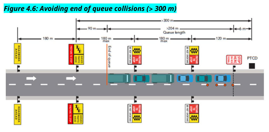
The duplication of the advance warning signs for a traffic control station as indicated in Figures 4.4, 4.5 and 4.6 below is not a specific requirement. Signs are to be duplicated in accordance with the requirements in Section 2.5.3 and Section 5.5.1 for speed signs.
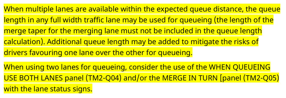
Figure 4.4 illustrates an example of sign positioning for queues as per the steps above for a speed of 60 km/h where the PREPARE TO STOP sign is less than or equal to 240 m away from the PTCD/traffic controller. This diagram is not an example of how to install all traffic control devices and is not to be used as a TGS diagram.
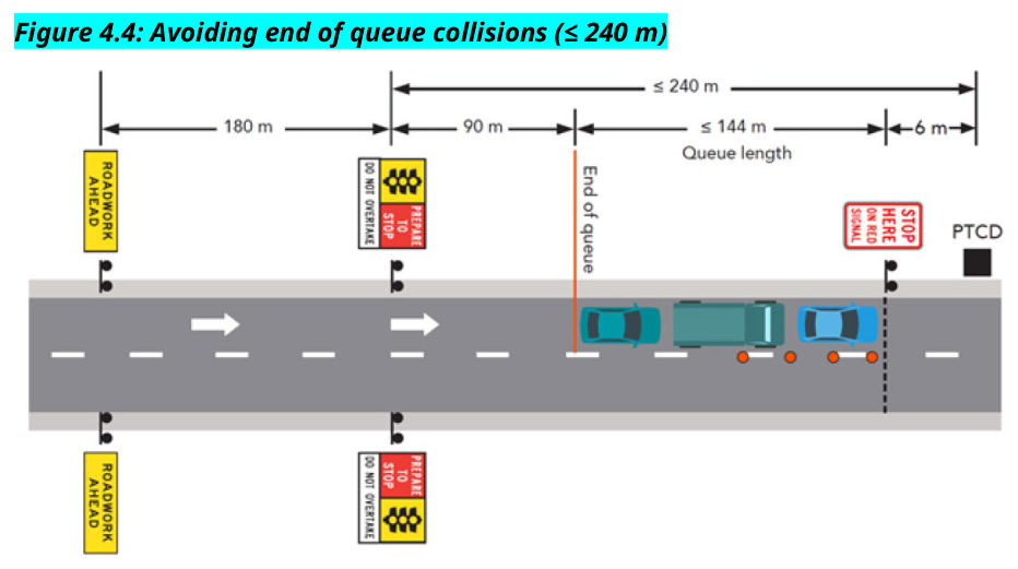
Figure 4.5 illustrates an example of sign positioning for queues as per steps above for a speed of 60 km/h where the primary PREPARE TO STOP sign is more than 240 m, but less than or equal to 300 m away from the PTCD/traffic controller. This diagram is not an example of how to install all traffic control devices and is not to be used as a TGS diagram.
Figure 4.6 illustrates an example of sign positioning for queues as per steps above for a speed of 60 km/h where the primary PREPARE TO STOP sign is more 300 m away from the PTCD/traffic controller. This diagram is not an example of how to install all traffic control devices and is not to be used as a TGS diagram.

While using two lanes for queuing is possible and may reduce the physical length of the queue, it does come with additional risks related to driver behaviour and capability. Lane utilisation may not be evenly distributed, as drivers often favour one lane over another, especially when approaching a merge point. Many drivers tend to merge earlier than necessary, which can cause the end of the queue to extend further back, and lead to increased end of queue risk. Driver aggression and frustration may also be experienced by those in the queue due to motorists cutting in late, which may not be the best frame of mind for drivers to be in when approaching the traffic control station or passing the workers on the site.
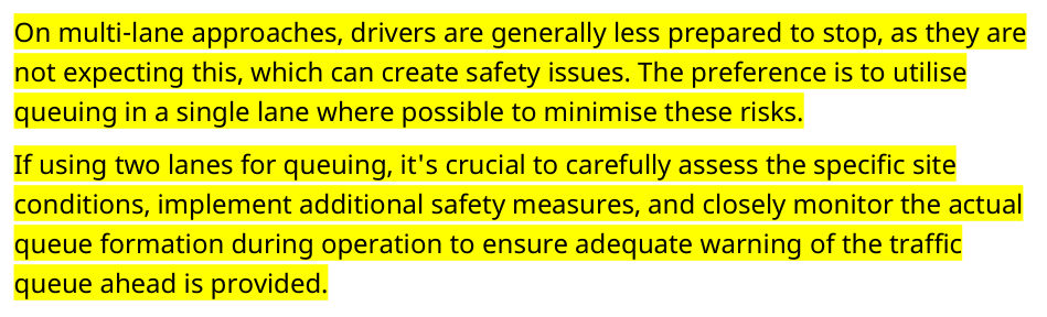
On multi-lane approaches, drivers are generally less prepared to stop, as they are not expecting this, which can create safety issues. The preference is to utilise queuing in a single lane where possible to minimise these risks.
If using two lanes for queuing, it's crucial to carefully assess the specific site conditions, implement additional safety measures, and closely monitor the actual queue formation during operation to ensure adequate warning of the traffic queue ahead is provided.
When multiple lanes are available within the expected queue distance, the queue length in any full width traffic lane may be used for queueing (the length of the merge taper for the merging lane must not be included in the queue length calculation). Additional queue length may be added to mitigate the risks of drivers favouring one lane over the other for queueing.
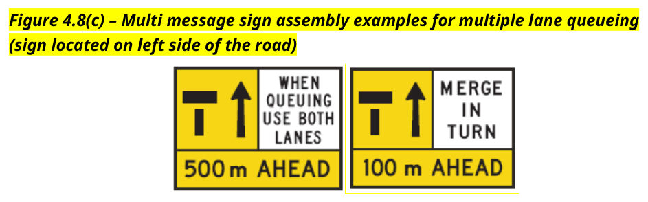
When using two lanes for queueing, consider the use of the WHEN QUEUEING USE BOTH LANES panel (TM2-Q04) and/or the MERGE IN TURN [panel (TM2-Q05) with the lane status signs.
Relaxed requirement for end of queue protection on low volume roads. TTM working group and the LGTTM working group have both raised concerns regarding the current approach which requires a lot of signs and devices on low volume roads. Current requirement was limited to higher speed roads by the permanent speed limit and this change allows for a volume threshold to be applied. See changes highlighted yellow following.
4.8.3Additional end-of-queue protection#
Where traffic control is in use, one or a combination of end-of-queue risk control measures in Chapter 1, Clause 2 of the Guideline – Traffic Management at Works on Roads must be implemented to manage the risk of rear end crashes where either of the following apply:
- the speed limit is 80 km/h or higher (prior to any reductions for the roadworks) and an annual average daily traffic (total vehicle count in both directions of travel per day) of over 500 vehicles per day
- where sight-distance to the end of the traffic queue is restricted (less than the value from Table 2.3).
End-of-queue risk control measures must also be implemented in Clause 5.8 of Annexure MRTS02.1 Provision for Traffic.
In addition to the requirements above, end-of-queue risk control measures should be considered and implemented to address end of queue risks at any site. Some considerations include:
- Where traffic slows significantly, or queues are formed due to congestion or roadworks.
- Where environmental or geometric issues exist that limit visibility or impact normal stopping distances such as poor weather conditions (for example rain or fog), poor road conditions, a downhill approach, vertical curves, night works (driver fatigue or visibility) or a slippery road surface are present.
- Where significant volumes of heavy vehicles are present or expected.
Provided updated guidance for several pedestrian and footpath related TTM considerations. Clarified information on providing alternative paths for pedestrians. Added information on the surfacing requirements for footpaths or alternative routes for pedestrians. Added a time consideration on the selection of an alternative route and surface type. Added consideration for tactile signs.