5.4Delineate the route#
Replace:
If narrower edge clearance is required, obtain approval from the relevant road infrastructure manager.
with:
If narrower edge clearances are required due to constrained geometry, the requirements of Clause 1.9 of the Queensland MUTCD Part 3 must apply.
Replace:
The spacing between delineation devices should be as detailed in Table 5.3.
with:
The maximum spacing between delineation devices should be as detailed in Table 5.3, excluding where the delineation devices are used to separate traffic from workers on foot, in which case the maximum spacing between delineation devices must be as detailed in Table 5.3.
Add the following note to Table 5.3:
Where the delineation devices are used to separate traffic from workers on foot, the maximum spacing between delineation devices must be as detailed above.
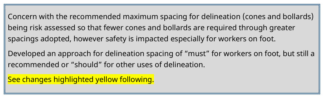
As above (Section 5.4), developed an approach for delineation spacing of “must” for workers on foot, but still a recommended or “should” for other uses of delineation. See changes highlighted yellow following.
5.4.1Traffic cones and bollards#
Replace the first dot point
- Maximum spacing of cones and bollards must be as shown in Table 5.3.
with
Maximum spacing of cones and bollards should be as shown in Table 5.3, excluding where the delineation devices are used to separate traffic from workers on foot, in which case the maximum spacing between delineation devices must be as detailed in Table 5.3.
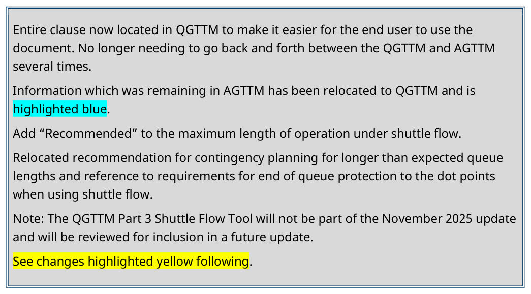
Entire clause now located in QGTTM to make it easier for the end user to use the document. No longer needing to go back and forth between the QGTTM and AGTTM several times.
Information which was remaining in AGTTM has been relocated to QGTTM and is highlighted blue.
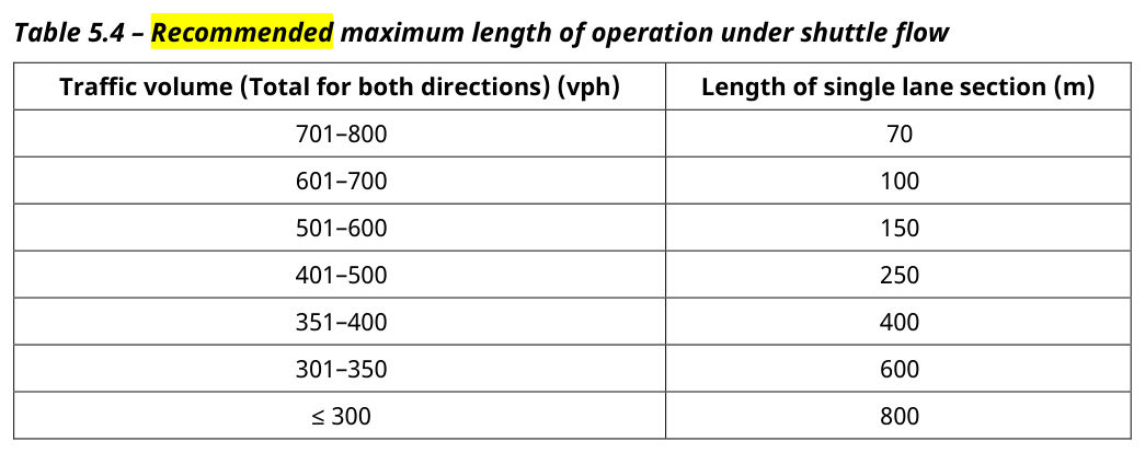
Add “Recommended” to the maximum length of operation under shuttle flow.
Relocated recommendation for contingency planning for longer than expected queue lengths and reference to requirements for end of queue protection to the dot points when using shuttle flow.
See changes highlighted yellow following.
5.4.4Shuttle flow#
Replace the entire Section 5.4.4 with the following:
Replace:
When using shuttle flow, the following are requirements and recommendations:
- Lane width should be reduced in accordance with Table 2.5. For further guidance on lane widths see Section 2.5.8.
- The swept path shall accommodate heavy and over-dimensional vehicles if required.
- Traffic control shall be provided at each end of the operation (see Section 5.10). Traffic control is not required if:
- o there is clear visibility past the work area and beyond it for at least 75 m, or to the end of the road if less than 75 m away
- o road users have clear visibility of the work area and the opposing approach for a distance greater than 150 m and either one of the following:
- traffic volume in both directions is 40 vph or less, and the speed is 70 km/h or less, and the length of the single lane is 60 m or less
- the length of the single lane is 100 m or less, and GIVE WAY and ONE LANE signs are provided at one end of the shuttle lane
- it is a residential street and the length of the shuttle is 60 m or less.
- Ensure single lane section lengths are a maximum distance as shown in Table 5.4.
with:
This method is typically used when a portion of the roadway is closed so that a single lane is used alternately by traffic travelling in opposite directions. It is one-way flow with one direction first, then the other.
When using shuttle flow, the following are requirements and recommendations:
- Lane widths must be in accordance with Table 2.5. For further guidance on lane widths, see Section 2.5.8.
- The swept path must accommodate heavy and over-dimensional vehicles if required.
- Active traffic control (by traffic controllers or PTCDs) must be provided at each end of the operation (see Section 5.10), except as follows:
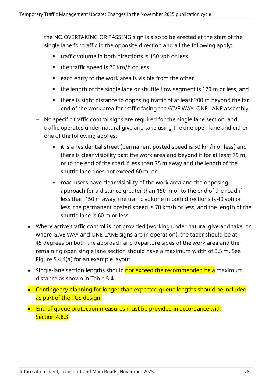
- ― GIVE WAY and ONE LANE signs are provided at one end of the shuttle lane and the NO OVERTAKING OR PASSING sign is also to be erected at the start of the single lane for traffic in the opposite direction and all the following apply:
- traffic volume in both directions is 150 vph or less
- the traffic speed is 70 km/h or less
- each entry to the work area is visible from the other
- the length of the single lane or shuttle flow segment is 120 m or less, and
- there is sight distance to opposing traffic of at least 200 m beyond the far end of the work area for traffic facing the GIVE WAY, ONE LANE assembly.
- ― No specific traffic control signs are required for the single lane section, and traffic operates under natural give and take using the one open lane and either one of the following applies:
- it is a residential street (permanent posted speed is 50 km/h or less) and there is clear visibility past the work area and beyond it for at least 75 m, or to the end of the road if less than 75 m away and the length of the shuttle lane does not exceed 60 m, or
- road users have clear visibility of the work area and the opposing approach for a distance greater than 150 m or to the end of the road if less than 150 m away, the traffic volume in both directions is 40 vph or less, the permanent posted speed is 70 km/h or less, and the length of the shuttle lane is 60 m or less.
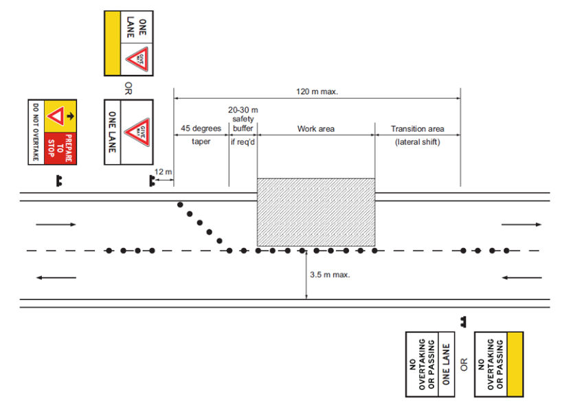
- Where active traffic control is not provided (working under natural give and take, or where GIVE WAY and ONE LANE signs are in operation), the taper should be at 45 degrees on both the approach and departure sides of the work area and the remaining open single lane section should have a maximum width of 3.5 m. See Figure 5.4.4(a) for an example layout.
- Single-lane section lengths should not exceed the recommended be a maximum distance as shown in Table 5.4.
- Contingency planning for longer than expected queue lengths should be included as part of the TGS design.
- End of queue protection measures must be provided in accordance with Section 4.8.3.
| Traffic volume (Total for both directions) (vph) | Length of single lane section (m) |
|---|---|
| 701–800 | 70 |
| 601–700 | 100 |
| 501–600 | 150 |
| 401–500 | 250 |
| 351–400 | 400 |
| 301–350 | 600 |
| ≤ 300 | 800 |
The volumes in Table 5.4 have been determined to allow a quick analysis without referring to a traffic engineering professional. Additional traffic engineering input is required to support a longer length of single-lane operation.
Generally, when using Table 5.4, and where the lengths are within the maximum limits, single-lane operation using active control by portable traffic control devices or traffic controllers will lead to a relatively short and consistent or stable queue length; however, additional traffic engineering input and considerations (risk assessments) are required to support longer lengths of single-lane operation which will generally lead to longer maximum queue lengths and queue lengths that are not easily managed, or are variable and unstable. Contingency planning for longer than expected or continually growing queue lengths shall be included as part of the TGS design. End-of-queue protection measures (see Section 4.8.3) shall be considered.
Figure 5.4.4(a) does not include all traffic control devices required and is not to be used as a TGS diagram.
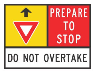
When GIVE WAY and ONE LANE signs are provided at one end of the shuttle lane (in accordance with this section), and advance warning of this arrangement is required, the Give Way Sign Ahead sign (W3-2 or WM3-2A in a multi-message sign assembly – see Figure 5.4.4(b) should be used.
Entire clause now located in QGTTM to make it easier for the end user to use the document. No longer needing to go back and forth between the QGTTM and AGTTM several times. Information which was remaining in AGTTM has been relocated to QGTTM and is highlighted blue