1Use of supplementary devices at roadworks to reduce speed#
1.1Purpose#
The purpose of this section is to provide options and guidance on the use of supplementary traffic control devices at roadwork sites to reduce the incidence of speeding within roadwork zones. One or a combination of treatment options shall be used when required by QGTTM Part 3, Section 4.8.3 or when specified in Clause 5.8 of Annexure MRTS02.1 Provision for Traffic. In addition to the requirements above, the use of supplementary traffic control devices at roadwork sites to reduce the incidence of speeding within roadwork zones may be considered and implemented at any site.
1.2Background#
The suite of signs and traffic control devices provided in the Queensland MUTCD has typically proved to be adequate and effective in achieving the desired result of reducing vehicle speeds at most roadworks sites. To improve safety for workers and road users, reduce the risk of incidents and increase the level of compliance with temporary speed limits, the following options can be used to supplement traffic control devices at roadwork sites:
- 1.speed indicator devices (Clause 1.3)
- 2.rumble strips/rumble mats (Clause 1.4)
- 3.UHF radio broadcast (Clause 1.5)
- 4.temporary speed humps (Clause 1.6)
- 5.variable message sign with automatic number plate recognition speed indicator device (Clause 1.7)
The use of a combination of different options to reduce traffic speeds at roadwork sites is permitted.
1.3Speed indicator devices#
1.3.1General#
Speed indicator devices use a radar unit which displays a vehicle’s speed with messages requesting a driver to SLOW DOWN if they are exceeding the speed limit or thanking those who are observed to be complying with the speed limit. The speed display is set to not display a speed in excess of 10 km/h over the speed limit to avoid drivers trying to record a high reading. Speed indicator devices are also capable of recording the speed of every vehicle that approaches the roadwork zone and can be used to determine speed characteristics through the roadwork zone.
Speed indicator devices may be installed at a roadwork site where speed compliance with the reduced roadwork speed limit is poor. The speed indicator device should be installed sufficiently in advance of locations where speed compliance is critical so that motorists have adequate time to read, comprehend the message and react accordingly to reduce speed. The speed indicator device should be programmed to display the speed and a SLOW DOWN message only to vehicles that are travelling over a set threshold.
1.3.2Technical requirements#
The speed indicator device should be capable of the following:
- 1.ability to display speed and message for a minimum period of five seconds
- 2.have a minimum 100 metre detection range and the ability to display a message every three seconds
- 3.provide remote access to the signs for the purpose of programming and data collection; this feature is only required for signs that are permanently installed for the duration of the project
- 4.provide adequate storage capacity to store data for up to one week
- 5.ability to obtain speed data and prepare reports using proprietary software for export to Excel file
- 6.ability to switch off the device remotely
- 7.operate through the use of solar power with battery back-up, and
- 8.be designed in accordance with TC1833 (other devices not conforming to TC1833 may be considered).
1.3.3Speed display#
The speed indicator device shall be set to activate as follows:
- 1.vehicles travelling less than or equal to speed limit: Display actual speed and THANK YOU message
- 2.vehicles exceeding speed limit by up to 10 km/h: Display actual speed and SLOW DOWN message, and
- 3.vehicles exceeding speed limit by more than 10 km/h: Display SLOW DOWN message only.
1.3.4Site installation#
The speed indicator device may be installed to improve speed compliance. Example locations include:
- 1.near excavations
- 2.where cyclists and pedestrians are present
- 3.where a Traffic Controller is operating
- 4.or where traffic signals or give way signs are installed, or
- 5.where workers on foot are present.
1.3.5Data collection#
If possible, data should be downloaded on a daily basis where traffic volumes are high to avoid loss of data through a full memory bank. The proprietary software available with the speed indicator device should be capable of data manipulation to determine average speed and 85th percentile speed of vehicles by time and day. The software should also be capable of filtering data by time and day. The software should also be capable of converting data to an Excel format for further analysis and reporting.
A record of traffic conditions, weather patterns, changes to signage, enforcement and other factors that may have an impact on driver behaviour should be kept.
1.4Rumble strips / rumble mats#
1.4.1General#
Rumble strips or rumble mats may be installed on the approach to the 60 km/h speed limit in a roadwork zone to make motorists aware of the reduced roadwork speed limit and to influence the driver to decrease speed.
1.4.2Installation#
Rumble strips shall only be installed where the following conditions are met:
- 1.the speed of traffic is less than the manufacturer’s recommended maximum, and
- 2.there is a minimum visibility distance of 80 m to the rumble strips / rumble mats.
1.4.3Technical requirements#
Rumble strips or rumble mats should only be used at roadwork sites when the reduced speed limit in the roadwork zone is required for the safety of the road worker or for traffic safety. Rumble strips or rumble mats should comply with the following:
- 1.rumble strips or rumble mats should not exceed 20 mm in thickness
- 2.rumble strips or rumble mats should be yellow in colour
- 3.should be installed without the need for tie down, and
- 4.should be easy to handle onsite and quick to install.
1.4.4Signage requirements#
Where rumble strips are installed at roadwork sites, an advance warning sign shall be installed to warn motorists of the rumble strip ahead (T1-Q18 or TM1-Q02). Rumble strip warning sign shall be installed adjacent to the rumble strip (TM2-Q02).
1.4.5Removal from site#
Rumble strips or rumble mats must only be used when the roadwork speed limit of 60 km/h is maintained. Rumble strips or rumble mats and all associated signage must be removed from site when the reduced speed limit is no longer required, and a higher speed limit is reinstated.
1.5UHF radio broadcast#
1.5.1General#
This system allows vehicles that are fitted with UHF radios to receive pre-recorded voice messages warning of traffic conditions ahead (for example, SLOW DOWN warnings) which can be automated or set to run periodically. Typical applications include:
- 1.SLOW DOWN notifications due to temporary road hazards ahead
- 2.changed traffic conditions ahead for temporary traffic-controlled sites
- 3.reduced speed ahead, and
- 4.other applications approved by the Intelligent Transport Systems and Electrical Unit.
1.5.2Technical requirements#
The UHF broadcast device shall comply with the following requirements:
- 1.The operating range of broadcast (km) of this type of system shall be up to 2 km; however, this will depend on the transmit power, type of antennae used (for example, directional Yagi / Omni Directional / Parabolic Dish antennae) as well as the usage of RF attenuators.
- 2.The frequency (band) is to be 477 MHz within the UHF band (300 MHz–3 GHz).
- 3.The RF equipment operating frequency shall not conflict with or cause interference to any other service within this band (such as Queensland Fire and Rescue Service, Queensland Police Service, Queensland Ambulance Service and other emergency services).
- 4.The RF equipment shall conform to all the requirements of the Australian Communications and Media Authority.
- 5.Pre-recorded messages shall be configured to play through external system activation (for example, induction loop detection, radar speed detection and other methods) or manual voice message on location.
- 6.Voice messages can be recorded onsite using a CB radio microphone unit or pre-recorded messages stored on external memory card (for example, SDRAM card).
- 7.All equipment shall be extra low voltage.
- 8.All equipment shall be protected from water ingress (minimum IP rating of IP67) and suitably robust and protected against damage from the elements.
- 9.All equipment shall be able to be easily handled by no more than two persons.
1.5.3Clearance from traffic lanes#
The UHF broadcast device shall be installed outside the clear zone required for that site or shall be shielded by means of barrier so that it does not present a hazard to errant vehicles.
1.6Temporary speed humps#
1.6.1General#
Speed humps may be used to increase compliance with the 40 km/h speed limit. The speed hump must be removed when the 40 km/h speed limit is no longer required (that is, when workers have left).
1.6.2Application of a speed hump device#
Prior to the use of any temporary speed hump device on a 40 km/h work site, a Traffic Guidance Scheme (TGS) shall be developed for the relevant work site. If higher order devices (such as safety barriers) are considered to be inappropriate temporary speed humps can be considered, subject to a risk assessment being undertaken.
These temporary speed humps shall only be used:
- 1.on a short-term roadworks site with a construction posted speed limit of 40 km/hr
- 2.as per the manufacturer’s specifications
- 3.in daylight hours or under floodlighting at each temporary speed hump location point
- 4.within the confines of the area defined by the relevant Traffic Guidance Scheme
- 5.in conjunction with appropriate warning signs; and
- 6.when the work site is attended (temporary speed humps shall be removed when no roadworks are being undertaken).
1.6.3Number of temporary speed humps at a work site#
Generally, a minimum of two temporary speed humps shall be used at a work site, one at each end of the road work area.
If the length of the work area is greater than 200 metres, or there is an interrupted line of sight between each end of the work zone, then intermediate temporary speed humps and their associated signing shall be installed at intervals of not less than 100 metres.
One temporary speed hump may be suitable for small work areas on local roads. The single temporary speed hump is to be located immediately prior to the work area.
In two directional arrangements, it may only be necessary to install temporary speed humps in the lane closest to the work site.
1.6.4Speed hump warning signs#
Temporary advance warning signs (TM1-38A) shall be installed in advance of the first temporary speed hump. TM1-38A shall be included in a multi message sign.
Warning signs (TM2-51A) shall be located at each of the temporary speed hump locations, including any intermediate temporary speed humps. These warning signs shall only be visible in the direction in which the hump is traversed (in the case of humps only being installed, in the lane closest to the work site).
1.6.5Speed hump installation requirements#
Speed humps shall be positioned to allow a bicycle rider to safely manoeuvre around the end of the hump without hitting any other object or hazard. A minimum clearance of 0.5 metres should be provided. Installation, maintenance and removal of temporary speed humps are to be as per the relevant manufacturer’s specifications. Traffic control, if required, shall be controlled by accredited Traffic Controllers during all installation, maintenance or removal activities.
1.6.6Delineation#
Where two-way traffic passes through the work area, there will be a need to ensure traffic does not attempt to bypass the temporary speed humps. Delineation may be required between each of the lanes to guide vehicles over the temporary speed humps.
Traffic cones and bollards should be considered for this purpose. Onsite procedures should be put in place to ensure traffic signs, cones and bollards are regularly inspected to ensure they are located in accordance with the Traffic Management Plan.
1.6.7Approved profiles#
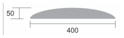
Speed humps are official traffic devices. The profile outlined in Figure 1.6.7 has been tested and the Department of Transport and Main Roads is satisfied that it is acceptable for the purpose of slowing vehicles without posing any driver control or behaviour concerns.
1.7Variable message sign with automatic number plate recognition speed indicator device#
1.7.1General#
Variable Message Signs (VMS) may use Automatic Number Plate Recognition (ANPR) devices with speed radar detection systems to provide travel speed feedback with number plate identification to drivers and may be installed at roadworks sites to encourage compliance with reduced roadworks speed limits.
1.7.1VMS / ANPR speed indicator devices#
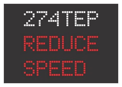
Like the speed indicator devices in Clause 1.3, VMS / ANPR speed indicator devices use a radar unit and display a vehicle's speed but, in addition, include the displays of the vehicle's registration plate as part of the feedback message. VMS / ANPR speed indicator devices also display messages requesting a driver to SLOW DOWN if they are exceeding the speed limit or thanking those who are observed to be complying with the speed limit. The speed display is set to not display a speed in excess of 10 km/h over the speed limit to deter drivers trying to record a high reading, but instead displays a REDUCE SPEED message (see Figures 1.7.4(a), (b) and (c) for display examples). VMS / ANPR speed indicator devices are also capable of recording the speed of every vehicle that approaches the device and can be used to determine speed characteristics through the roadworks zone. VMS / ANPR speed indicator devices, when used, should be installed sufficiently in advance of the area so motorists have adequate time to read, comprehend the message and react accordingly to reduce their speed. The location of the VMS / ANPR device shall be included on the Traffic Guidance Scheme (TGS).
1.7.2Technical requirements#
The VMS / ANPR speed indicator device should be capable of the following:
- 1.ability to display speed, vehicle registration, and message for a minimum period of five seconds
- 2.have a minimum 100 metre detection range and the ability to display a message every three seconds
- 3.provide remote access to the signs for the purpose of programming and data collection; this feature is only required for signs that are permanently installed for the duration of the project
- 4.provide adequate storage capacity to store speed data for up to one week
- 5.ability to obtain speed data and prepare reports using proprietary software for export to Excel file
- 6.ability to switch off the device remotely
- 7.operate through the use of solar power with battery back-up
- 8.on two-way roads, the device's radar and ANPR units only capture traffic approaching the device (roadworks zone) and not traffic travelling away from the device, or have the device's radar and ANPR units able to be angled as per Clause 1.7.5 (4) to achieve this outcome, and
- 9.on multi-lane roads, the device must be capable of detecting vehicle speeds and reading number plates for all lanes of traffic on approach to the device and be able to pair the relevant speed and number plate data accurately per lane, or the device cannot be used on multi-lane roads.
The VMS is to be designed in accordance with requirements of Technical Specification MRTS262 Transportable variable message signs.
1.7.3Variable message sign size#
There are three different sizes of VMS (Type A, B and C) in Australian Standard AS 4852.2 Variable message signs Part 2: Portable signs, and their use is dependent on the traffic speed where they are located. The VMS size shall be included on the TGS and should be as per Table 1.7.3 following.
| Traffic speed | VMS |
|---|---|
| ≤60 | Type A |
| 61–90 | Type B |
| >90 | Type C |
1.7.4Variable message sign message display#
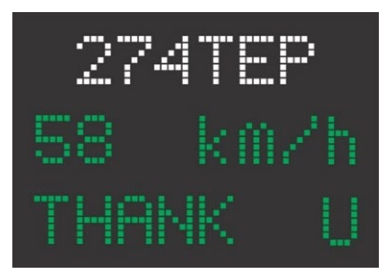
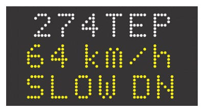
Due to the configuration of the VMS display in AS 4852.2, consisting of a matrix of three lines of eight characters per line, the messages displayed shall conform with this requirement. Due to this, the messages for items 1 and 2 following have been abbreviated. Where the VMS is capable of displaying the full words, 'THANK YOU' or 'SLOW DOWN' should be displayed unabbreviated. Where possible, the messages should be centred on the display screen.
The VMS / ANPR speed indicator device shall be set to activate as follows:
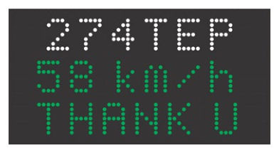
- 1.vehicles travelling less than or equal to speed limit: display vehicle registration number, actual speed and 'THANK U' message, see Figure 1.7.4(a) for examples
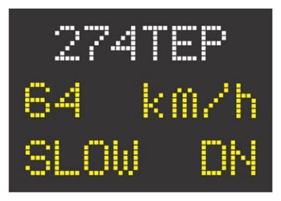
- 2.vehicles exceeding speed limit by up to 10 km/h: display vehicle registration number, actual speed and 'SLOW DN' message, see Figure 1.7.4(b) for examples, and
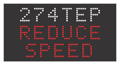
- 3.vehicles exceeding speed limit by more than 10 km/h: display vehicle registration number and 'REDUCE SPEED' message only, see Figure 1.7.4(c) for examples.
While the colour for fonts displayed on VMS screens is typically yellow, the use of green fonts (for item 1) and red fonts (for item 3) shall be used for VMS / ANPR speed indicator devices to assist quick glance understanding by drivers. Additionally, to separate the vehicle registration number from the message, the vehicle registration number shall be displayed in a white font (see Figures 1.7.4(a), (b) and (c) for display examples). VMS / ANPR speed indicator devices shall use a single screen per message and shall not be used for other messages while being used as a VMS / ANPR speed indicator device.
1.7.5Site installation#
The VMS / ANPR speed indicator device shall be located in accordance with the provisions for VMS devices in AGTTTM and QGTTM Part 3, Section 6.10 in addition to the following:
- 1.the device should be close enough to the travelled path to enable approaching drivers to easily read the device as they pass
- 2.when located on the shoulder of the road, the devices shall be a minimum of 1.5 m clear of the travelled path (including any space for cyclists)
- 3.the device shall be separated from all other signs by at least one sign spacing
- 4.on two-way roads, the device's radar and ANPR units should be angled to capture vehicle speeds and number plates for traffic approaching the device only, and
- 5.on multi-lane roads, the device's radar and ANPR units should be angled to capture vehicle speeds and number plates for all lanes of traffic on approach to the device.
1.7.6Data collection#
Speed and volume data shall be recorded and retained and logged for later retrieval. ANPR data for the display of vehicle registration numbers shall only be required during the display of that vehicle's speed and shall not be recorded for future use.
If possible, speed and volume data should be downloaded on a daily basis where traffic volumes are high to avoid loss of data through a full memory.
The proprietary software available with the VMS / ANPR speed indicator device should be capable of data manipulation to determine average speed and 85th percentile speed of vehicles by time and day. The software should also be capable of filtering data by time and day. The software should also be capable of converting data to an Excel format for further analysis and reporting.
A record of traffic conditions, weather patterns, changes to signage, enforcement and other factors that may have an impact on driver behaviour should be kept.