2.6Example figures for VSL / LC signs used for roadworks#

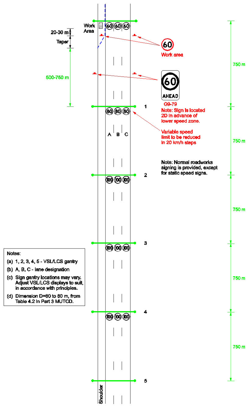
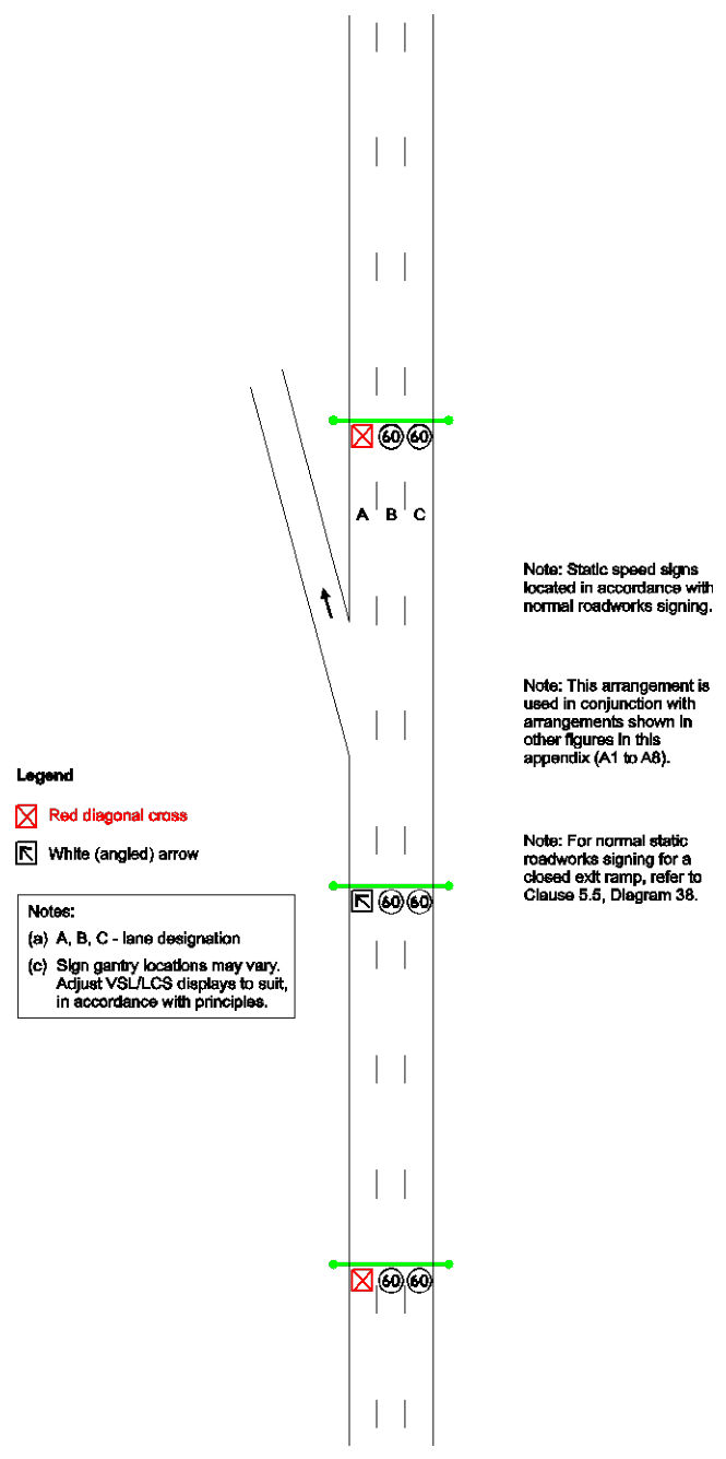
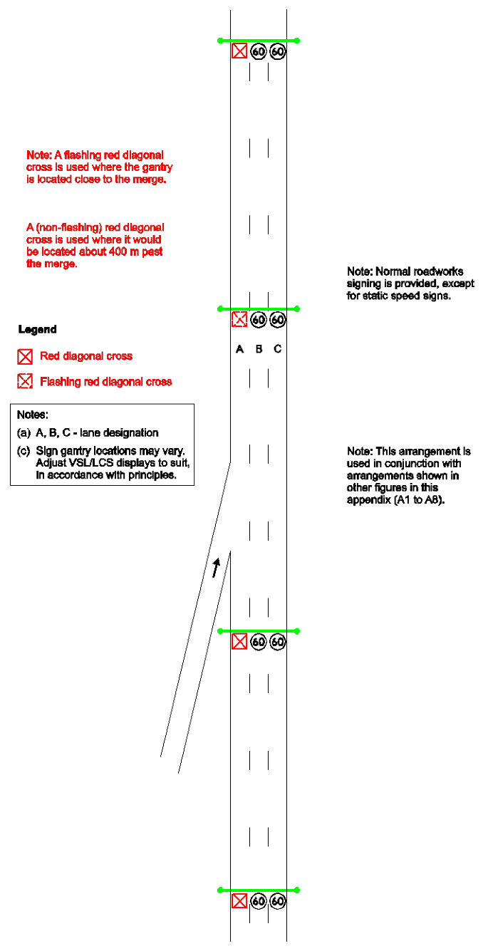
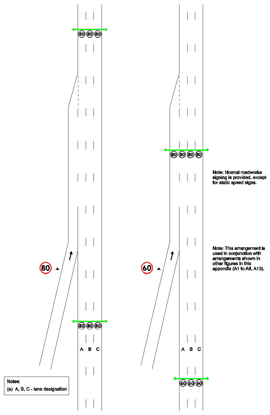
Typical arrangement figures which illustrate the application of variable speed limit and lane control signals to various work site situations are shown in Section 2.5 of this chapter. These figures indicate a nominal spacing of 750 m; however, the spacing between gantries may be larger or smaller depending on road geometry. Work site situations which are not specifically covered by the figures should be signed by adopting the most appropriate figure according to the principles outlined in this chapter.
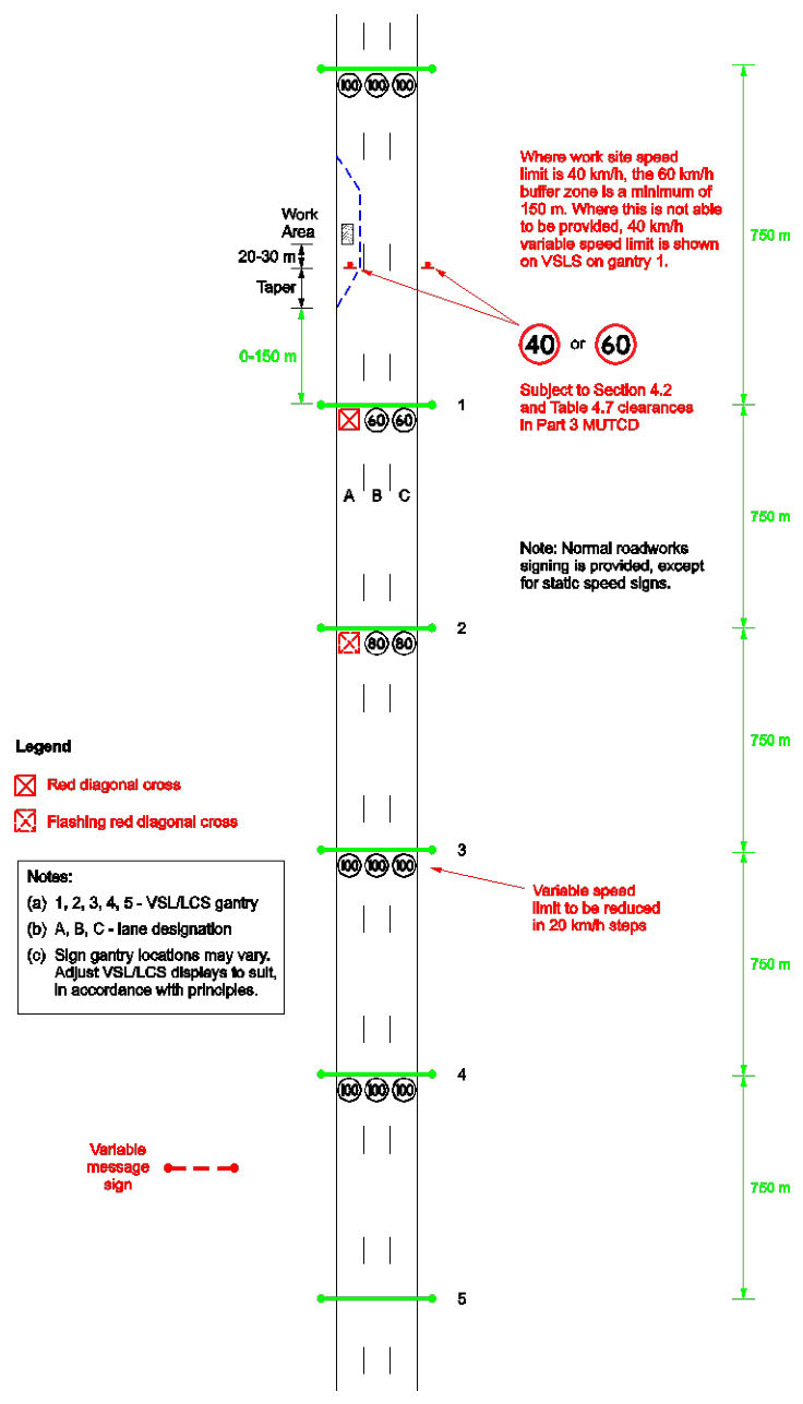
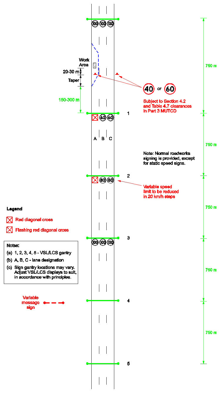
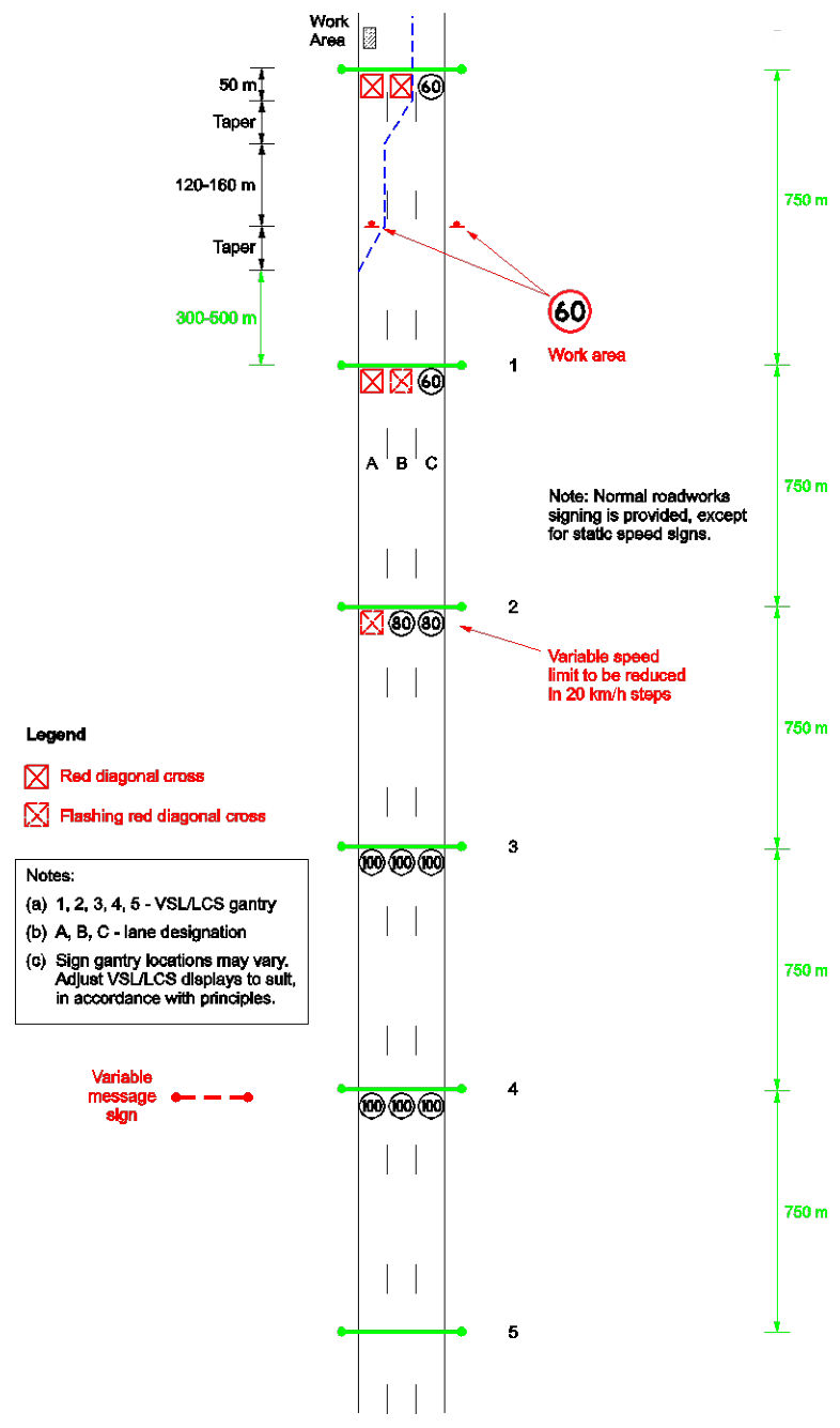
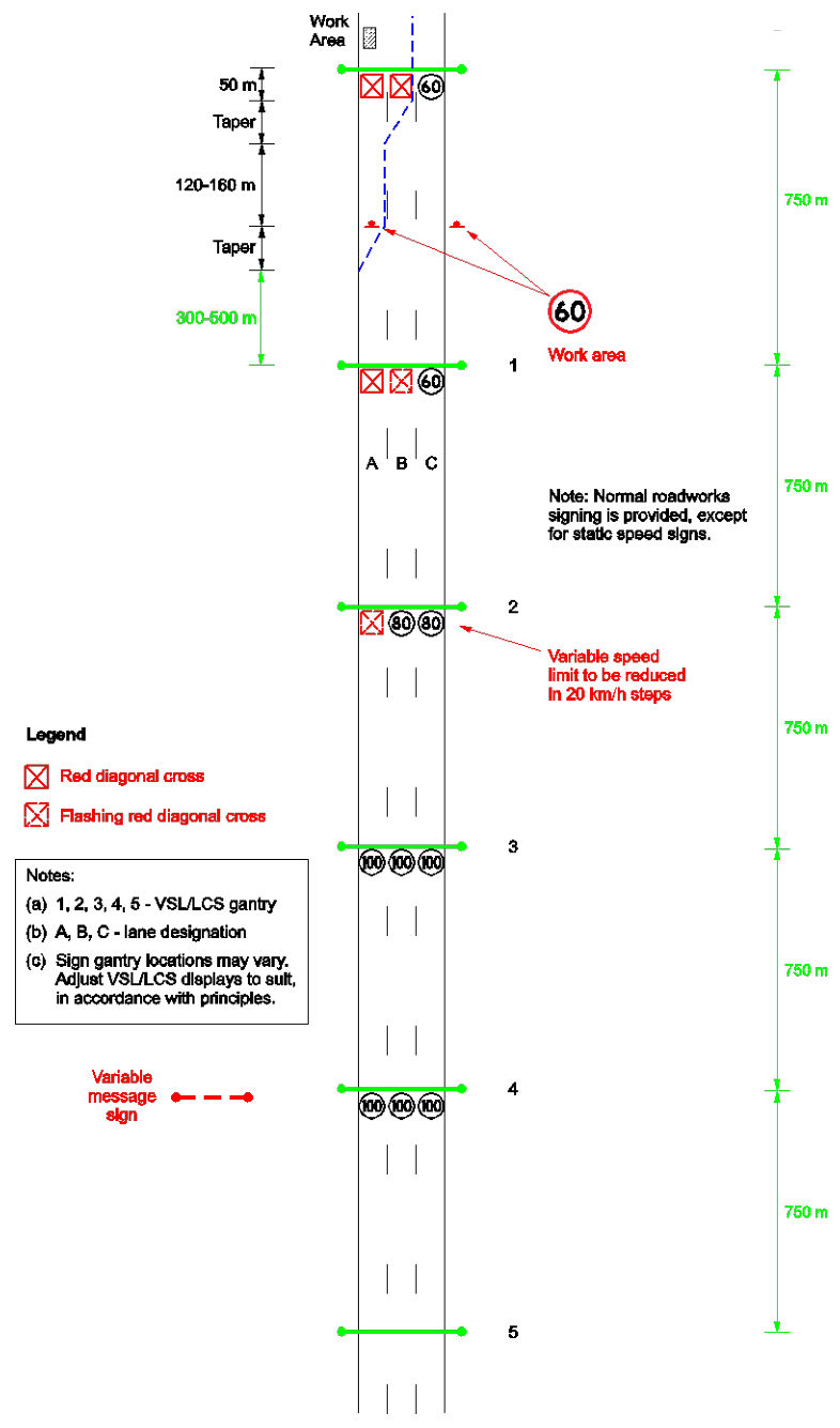
Figure 2.6(a) – Work in one lane – 0–150 m
Figure 2.6(a) – Work in one lane – 0–150 mp. 38
Figure 2.6(b) – Work in one lane – 150–300 m
Figure 2.6(b) – Work in one lane – 150–300 mp. 39
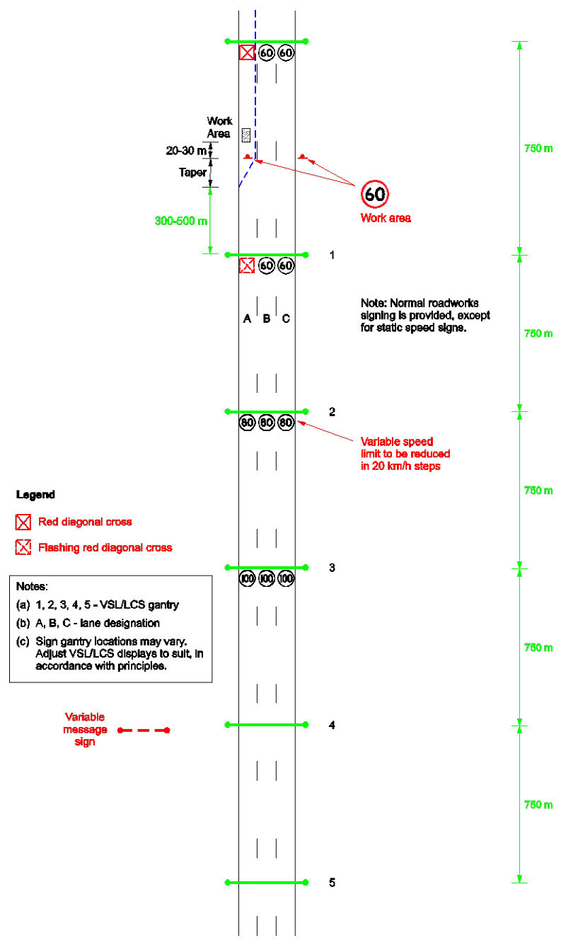
Figure 2.6(c) – Work in one lane – 300–500 m
Figure 2.6(c) – Work in one lane – 300–500 mp. 40
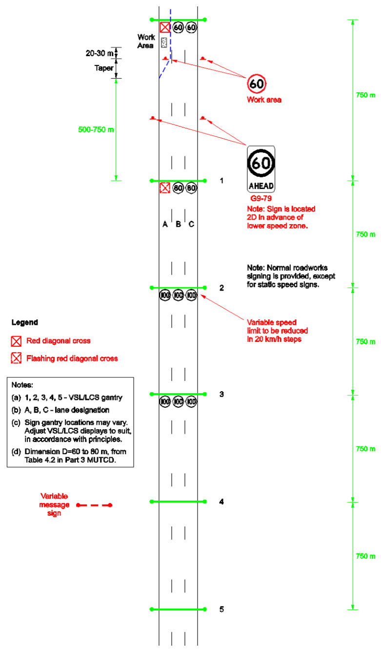
Figure 2.6(d) – Work in one lane – 500–750 m
Figure 2.6(d) – Work in one lane – 500–750 mp. 41
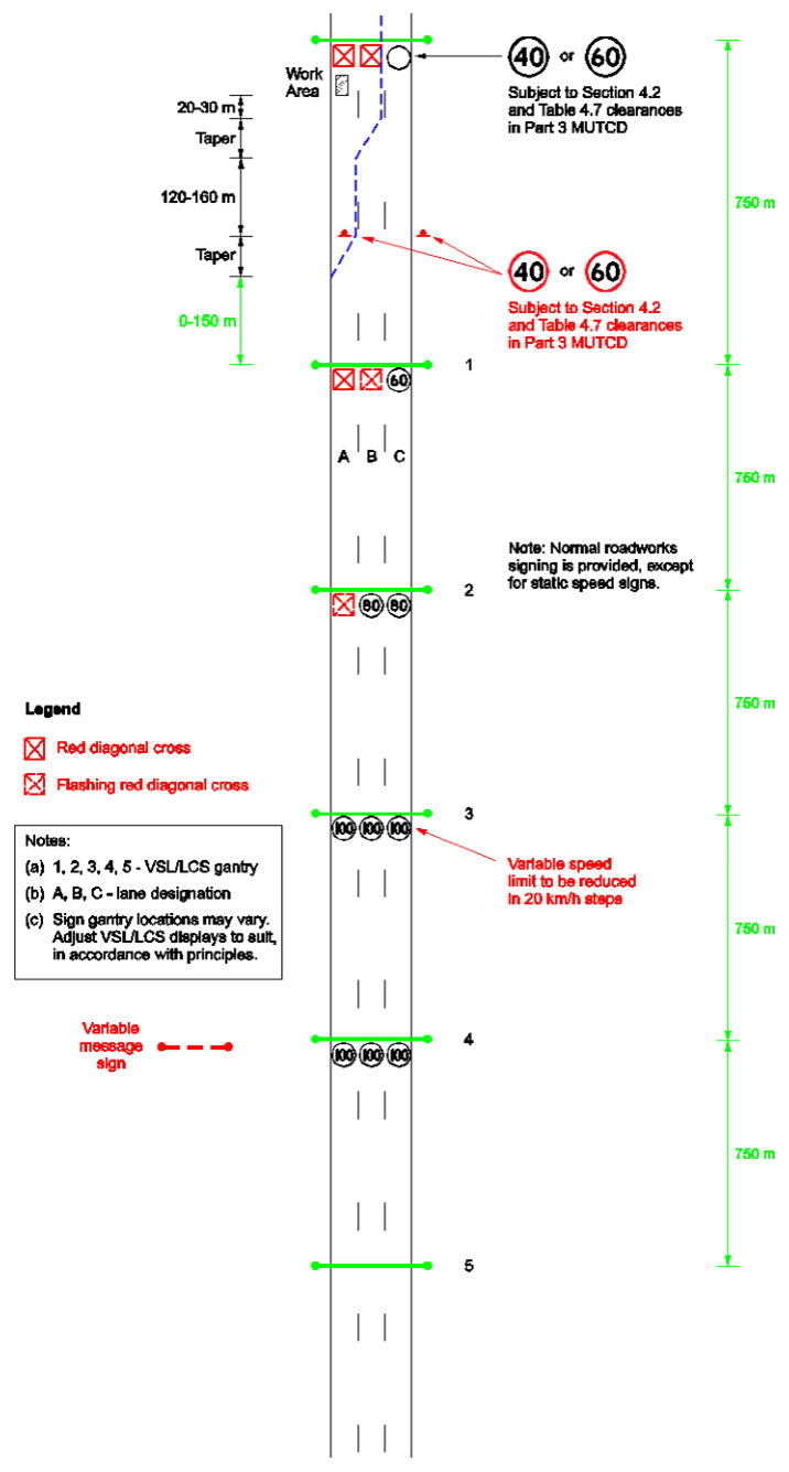
Figure 2.6(e) – Work in two lanes – 0–150 m
Figure 2.6(e) – Work in two lanes – 0–150 mp. 42
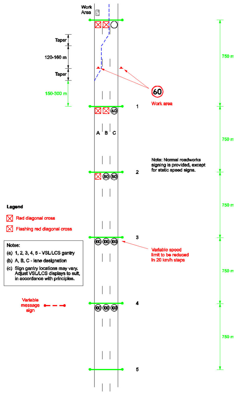
Figure 2.6(f) – Work in two lanes – 150–300 m
Figure 2.6(f) – Work in two lanes – 150–300 mp. 43
Figure 2.6(g) – Work in two lanes – 300–500 m
Figure 2.6(g) – Work in two lanes – 300–500 mp. 44
Figure 2.6(h) – Work in two lanes – 500–750 m
Figure 2.6(h) – Work in two lanes – 500–750 mp. 45
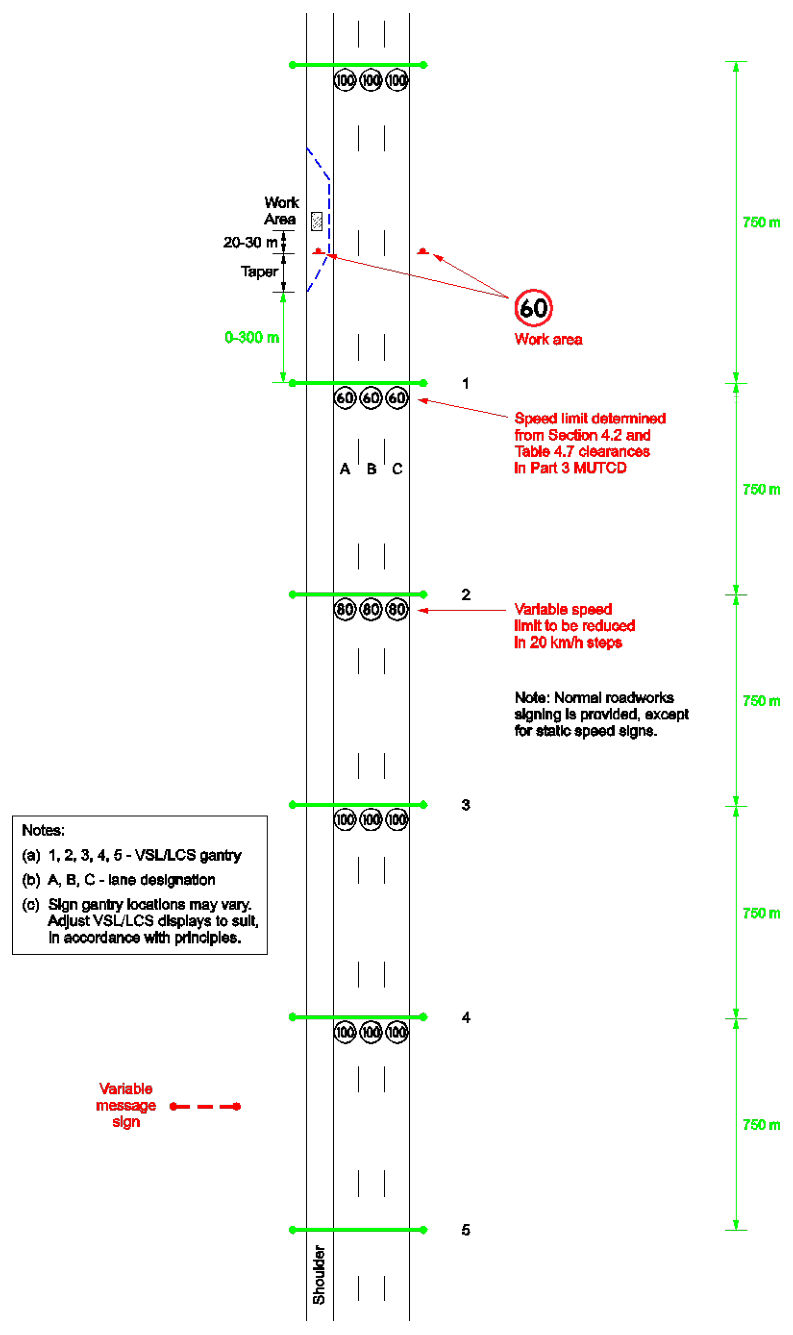
Figure 2.6(h) – Work on shoulder – 0–300 m
Figure 2.6(h) – Work on shoulder – 0–300 mp. 46
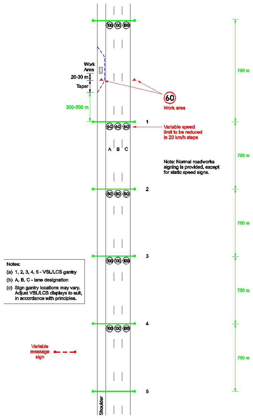
Figure 2.6(i) – Work on shoulder – 300–500 m
Figure 2.6(i) – Work on shoulder – 300–500 mp. 47
Figure 2.6(j) – Work on shoulder – 500–750 m
Figure 2.6(j) – Work on shoulder – 500–750 mp. 48
Figure 2.6(k) – Lane closed across an exit ramp
Figure 2.6(k) – Lane closed across an exit rampp. 49
Figure 2.6(l) – Lane closed across an entrance ramp
Figure 2.6(l) – Lane closed across an entrance rampp. 50
Figure 2.6(m) – Variable speed limits at entrance ramp merge
Figure 2.6(m) – Variable speed limits at entrance ramp mergep. 51
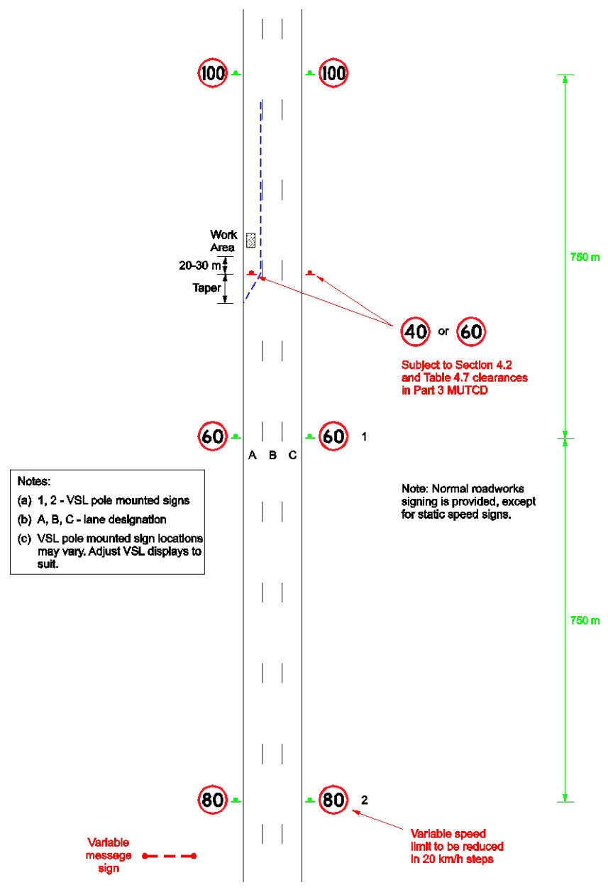
Figure 2.6(n) – Work in one lane – pole mounted VSL signs
Figure 2.6(n) – Work in one lane – pole mounted VSL signsp. 52
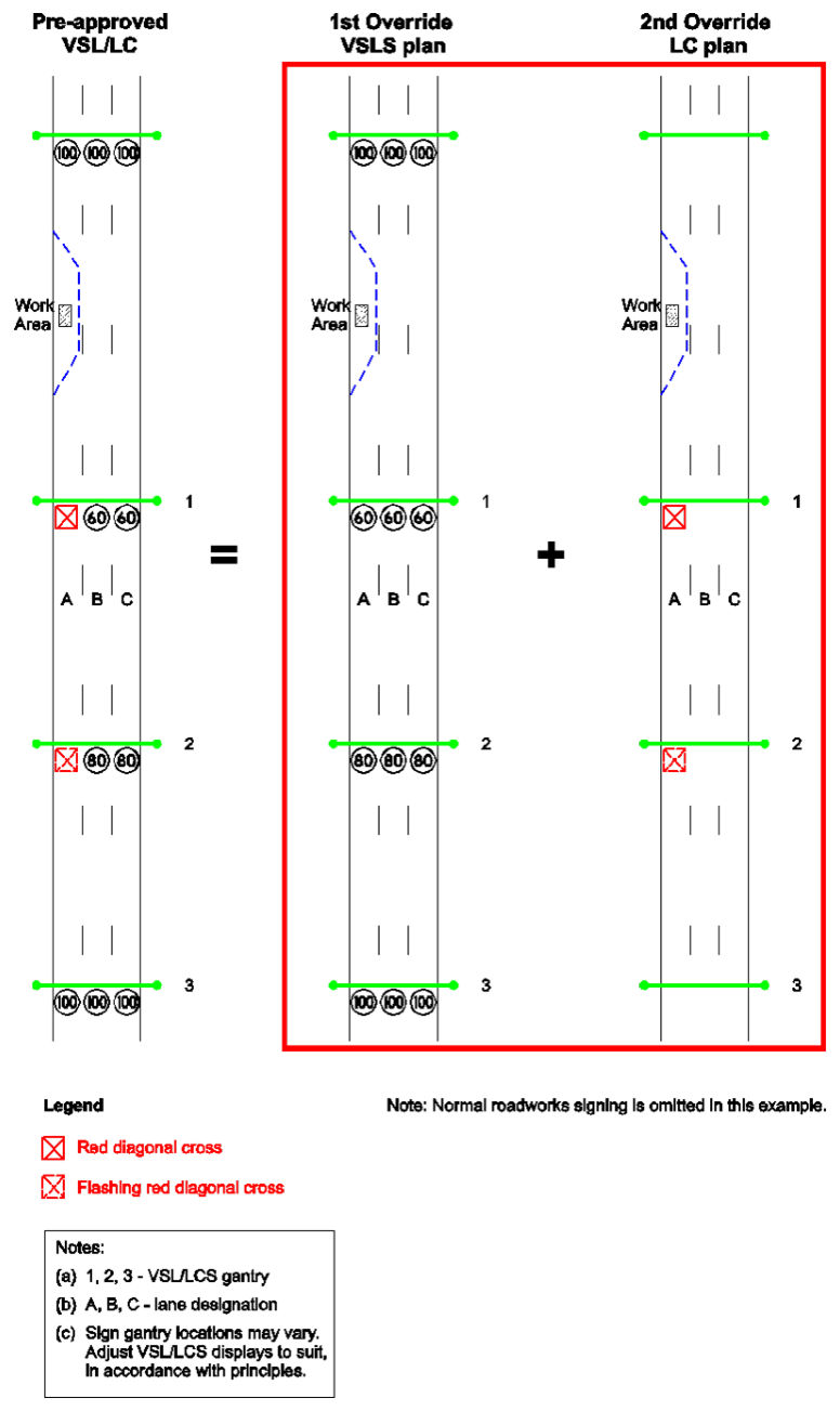
Figure 2.6(o) – Staged implementation of pre-approved VSL / LC plan
Figure 2.6(o) – Staged implementation of pre-approved VSL / LC planp. 53
Source: TM at Works on Roads Guideline · pages 37–53 Open PDF at this page Search this document