2.1Definitions#
Table 2.1(a) and Table 2.1(b) show relevant definitions and acronyms for this section.
Table 2.1(a) – Definitions
| Term | Definition |
|---|---|
| buffer | A buffer is a speed zone, of minimal length, and intermediate value between two speed limits that differ by more than 20 km/h; for example, an 80 km/h buffer zone would generally be used as a transition between speed limits of 100 km/h and 60 km/h. |
| critical fault | A critical fault of the variable speed limit system is a fault that may cause an unsafe situation for the site personnel. |
| default speed limit | In case of failure of the variable speed limit system, it is necessary to specify a speed limit for motorists to travel at. This is called the default speed limit and will be set to normal posted speed limit (had the road been a static speed zone). |
| non-critical fault | A non-critical fault of the variable speed limit system is a fault that does not affect the safety of the work site. A non-critical fault might be when a small number of LEDs fail. |
| secondary contact | A person delegated by the Site Supervisor as the secondary contact person for onsite personnel. The TMC Supervisor or Operator will contact this person in the instance that the Site Supervisor is not able to be contacted. |
| Site Supervisor | The Site Supervisor is the person responsible for works. This person will be the primary contact for onsite personnel. The TMC Supervisor or Operator will contact this person to coordinate the activation, deactivation and management of the electronic signs. |
| STREAMS® | STREAMS® Integrated Intelligent Transport System is an enterprise traffic management system developed by the Department of Transport and Main Roads that applies information and communications technology to transport operations to reduce operating costs, improve safety and maximise the capacity of existing infrastructure. STREAMS® provides traffic signal management, incident management, motorway management, vehicle priority, traveller information, flood monitoring and parking guidance within a single integrated system. |
| TGS | The Traffic Guidance Scheme (TGS) is an arrangement of temporary signs and devices to warn traffic and guide it through or past a work area or temporary hazard. |
| TMC Operator | This person in the Traffic Management Centre is responsible for activating, deactivating and managing the electronic signs. This person is responsible for communications with the Site Supervisor and other site personnel. |
| TMC Supervisor | This person is responsible in the Traffic Management Centre for overseeing operations and approvals. |
| transition | Transitions are automatically implemented by the system and form the intermediate arrangement of signs to allow a smooth conversion between the current and the desired state of signs. Consider the following example of a sign which currently displays 100 km/h: before changing that specific sign to 60 km/h, this sign must transition through an 80 km/h speed limit for a minimal time. |
| Term | Definition |
|---|---|
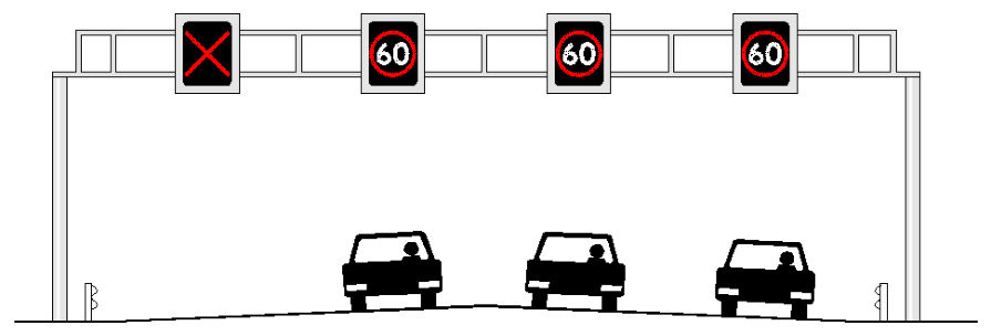
| variable speed limit zone | A variable speed limit zone is defined as a length of road which is controlled by variable speed limit signs. Static speed limits are not used. A variable speed limit zone may also include lane control signs to open and close lanes. |
Table 2.1(b) – Acronyms
| Acronym | Expansion |
|---|---|
| ITS | Intelligent Transport System |
| LCS | Lane control sign |
| TGS | Traffic Guidance Scheme |
| TMC | Traffic (or Transport) Management Centre |
| TMP | Traffic Management Plan |
| VSLS | Variable speed limit sign |
| VSL / LCS | Variable speed limit and lane control sign (integrated) |