8Pavement marking and patches for toll roads#
8.1Purpose#
The purpose of pavement patches for toll roads is two-fold:
- 1.to provide supplementary guidance for drivers seeking to access the toll road, by reassuring drivers they are in the correct lane, and
- 2.to warn drivers who do not intend to enter the toll road and provide them with an opportunity to change lanes, particularly when placed in a lane that goes exclusively to a toll road (a ‘trap lane’).
8.2General#
To further highlight the entrances to toll roads, a pavement marking option has been developed which comprises the route number (for example, M7) or an identifier for the toll road. Refer to TC1963 and TC2055 respectively for detailed patch design requirements and Section 3.3 for design principles. Pavement marking (yellow on blue patch) shall be placed in a lane that goes exclusively to a toll road (a 'trap lane').
8.3Design and location#
The design and location requirements for the use of pavement marking to assist driver navigation onto or away from toll roads include:
- pavement marking messages (including toll road patches) are in addition to any direction signs and standard arrow markings required
- a choice of destination(s), road names, route numbers or other relevant symbols may be used as appropriate pavement marking or patches, however:
- − the preference is that route numbers should be used if appropriate, and
- − it is recognised that, in some cases, 'CITY' or other short key destination message would be equally effective as the route number and may be used as appropriate
- providing pavement marking in lanes other than a trap lane is useful to provide additional reassurance for drivers who wish to either use or not use the toll road of which lane they should be travelling in
- an arrow should be provided within the pavement patch at the location where drivers enter the toll road–– this patch (with arrow) is only located at or just in advance of:
- − the commencement of the continuity line at the exit point
- − the start of the continuity line if an exit to a non-tolled road is possible at the gore point for a trap lane, and
- − the start of a trap lane (change in lane line marking) to a toll road
- if a pavement patch is provided in a lane that has a dual destination, consider also marking the alternative destination on the pavement:
- − where the alternative destination is marked along with a toll road patch, at the location where the lanes diverge laterally and both lanes are fully developed, the driver should see the toll patch in one lane and the alternative destination patch in the other (at roughly the same time), and
- − typically, these are located just past the gore point
- spacing between dual patches or patches and legend shall be 12–24m on high-speed roads and 1.25–2.5m on low speed roads – the order of the patches is not critical; however, in the interest of consistency, the toll patch should be installed prior to the other patches / legend
- if standard pavement arrows are required or installed, locate the toll road patches prior to the pavement arrows with a separation to the pavement arrows of 12–24m on high-speed roads and 1.25–2.5m on low-speed roads
- on high-speed (80 km/h or greater speed limit) roads, the patches are to be placed approximately 120m beyond each advance direction sign, to allow drivers to comprehend the sign message first and then link the message to the patches on the road located approximately four seconds of travel beyond the signs:
- − if standard pavement arrows are required or installed at this location, locate the patches prior to the pavement arrows with a separation to the pavement arrows of 12–24m, and
- on low speed (less than 80 km/h speed limit) roads, the patches are to be placed a short distance (12–24m) beyond each advance direction sign:
- − if standard pavement arrows are required or installed at this location, locate the patches prior to the pavement arrows with a separation to the pavement arrows of 1.25–2.5m.
8.4Examples of pavement patches to identify toll roads#
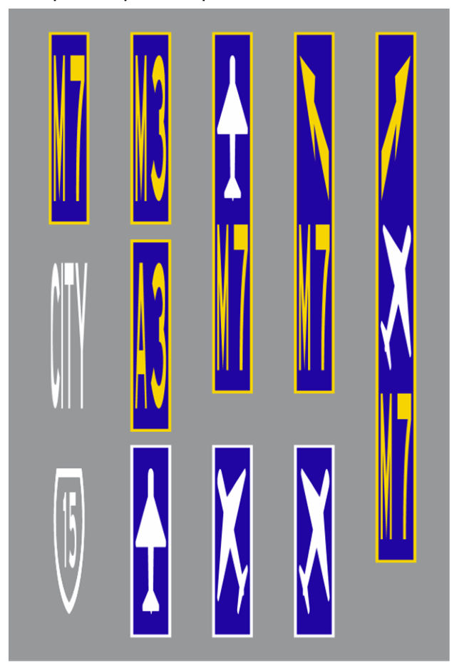
A number of different toll road pavement patch examples are provided following in Figure 8.4.
8.5High speed motorway example (M3 northbound approaching M7 exit)#
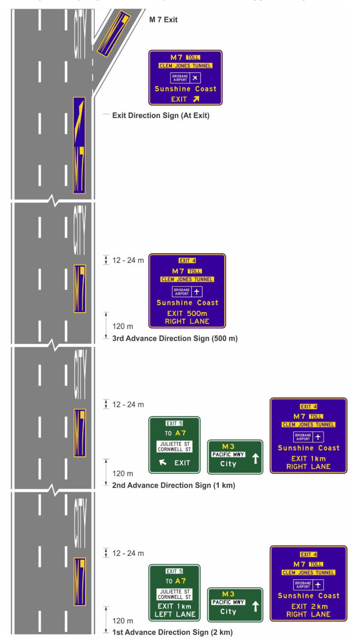
Toll road pavement patches in motorway environments are generally located with the associated direction signs and at the lane change / exit locations. Figure 8.5 shows the pavement marking for the Pacific Motorway (M3) northbound on approach to the exit ramp for the Clem Jones Tunnel (M7) which is a toll road and could be adapted to suit any standard motorway exit.
The following is a descriptive sequence along the Pacific Motorway from the initial advance exit direction signs to the tunnel through to the exit ramp:
- 1st advance direction sign (at 2km from the exit ramp)
- − M7* patch and CITY legend in M3 RH (right hand) lane 120m downstream from the direction sign with a spacing of 12–24m between the patch and the legend
- 2nd advance direction sign (at 1km from the exit ramp)
- − M7* patch and CITY legend in M3 RH lane 120m downstream from the direction sign with a spacing of 12–24m between the patch and the legend
- 3rd advance direction sign (at 500m from the exit ramp)
- − M7* patch and CITY legend in M3 RH lane 120m downstream from the direction sign with a spacing of 12–24m between the patch and the legend
- 4th direction sign (at the exit point – start of continuity line)
- − M7* patch with arrow adjacent to start of the exit continuity line
- At the point at which the full off-ramp lane width is developed (at the exit gore)
- − M7* patch in the fully developed off-ramp lane and CITY legend in the continuing M3 RH lane.
The M7 Patch in the previous example is yellow legend on a blue background inside a yellow border, while the CITY legend is white only.
8.6Low-speed road example (Stafford Rd eastbound approaching Airport Link Tunnel entry)#
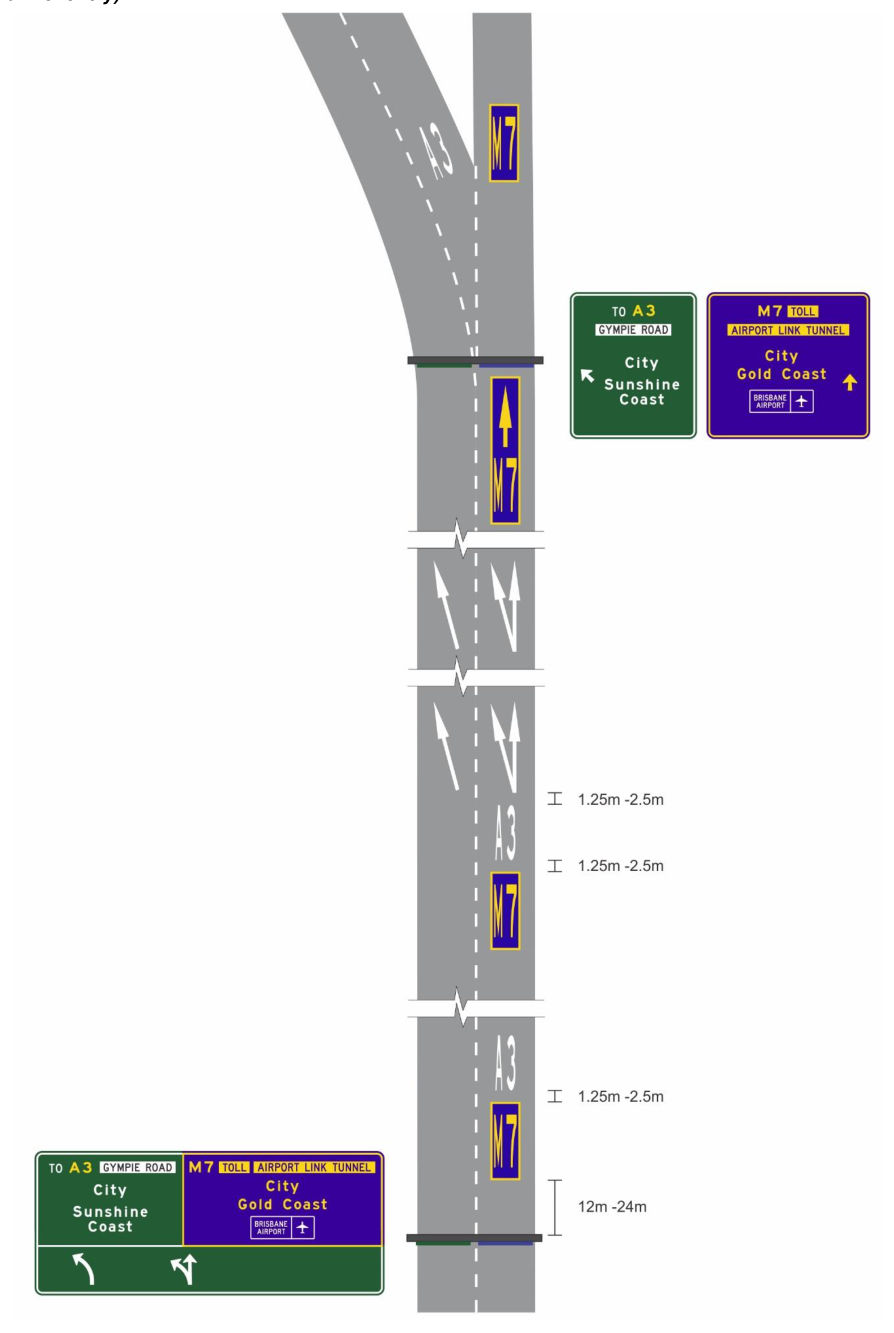
Toll road pavement patches in lower speed environments are generally located with the associated direction signs, pavement arrows and at the lane change / exit locations. Figure 8.6 shows Stafford Road (Metroad 5) eastbound on approach to the Airport Link tunnel (M7) which is a toll road and Gympie Road (A3). This example could be adapted to suit any standard low speed road.
The following is a descriptive sequence along Stafford Road from the initial advance exit direction signs to the tunnel through to the exit ramp.
- 1st advance direction sign (at approximately. 300m from the tunnel entry ramp)
- M7 patch and A3 symbol in RH (right hand) lane 12–24m downstream from the direction sign with a spacing of 1.25–2.5m between the patches
- 1st Pavement Arrows (at 170m from the tunnel entry ramp) – not shown in Figure 8.6
- no patches at this location
- 2nd Pavement Arrows (at 120m from the tunnel entry ramp)
- M7 patch and A3 symbol in RH lane 1.25–2.5m prior to the pavement arrows with a spacing of 1.25–2.5m between the patches
- 3rd Pavement Arrows (at 60m from the tunnel entry ramp – prior to start of continuity line)
- no patches at this location
- At the exit point to the tunnel entry ramp – start of continuity line
- M7 patch with arrow adjacent to start of the continuity line
- At the point at which both the tunnel entry ramp and the alternative route lane widths are fully developed (at the exit gore)
- M7 patch in the fully-developed tunnel entry ramp RH lane and A3 symbol in the LH lane.
The M7 Patch in the previous example is to be a yellow legend on a blue background inside a yellow border, while the A3 symbol will be in a white legend only.
Stafford Road (Metroad 5) finishes at the Gympie Road intersection (a short distance ahead); however, if Metroad 5 was to continue beyond this point, the A3 symbols would be replaced with the Metroad 5 symbol.