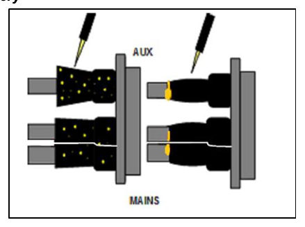
11Installation instructions – active joint#
11.1Active connector#
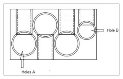
SELECT HOLE – Select hole in connector to suit cable size.
‘Holes A’ can accommodate cables 16–35 mm²
‘Hole B’ can accommodate cables 2.5–6 mm².
11.2Remove insulation and make connection#
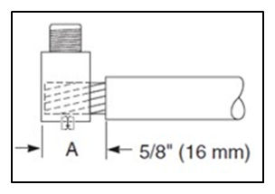
REMOVE INSULATION – Insulation removal length equals connector insertion depth (16 mm), allowing gap between insulation and connector.
INSERT CONDUCTORS – Insert conductors into connector
TIGHTEN SCREWS – Using a torque wrench, tighten screws to the appropriate torque value.
Hole A: 3 Nm
Hole B: 3 Nm
11.3Push sealing cap onto connection#
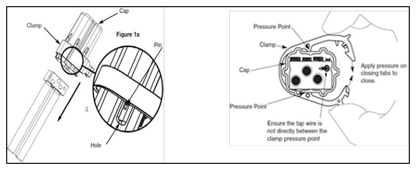
INSTALL CAP – Install cap by holding all wires and pushing the cap over the connection assembly until it goes no further.
INSTALL CLAMP – Install clamp on cap. Verify proper placement of clamp by ensuring the two pins on the bottom edge of the clamp are mated with the holes of the cap, as shown in the figure following.
APPLY PRESSURE – Apply pressure to close, using pliers if necessary. Clamp pressure points should fit into opposing grooves of cap and apply pressure between the cables.