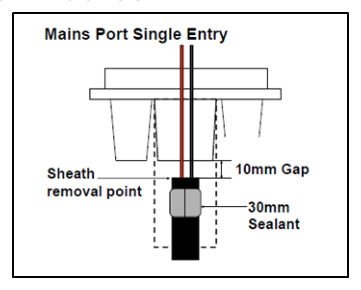
8Apply grey sealant to cables#
8.1All power cables#
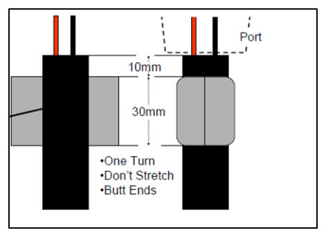
CUT TAPE – Cut the sealant tape to fit one turn around cable.
APPLY TAPE – Apply tape to sheath 10 mm back from cut.
DO NOT STRETCH – Do not stretch sealant tape.
BUTT ENDS – Butt ends of tape together without overlap.
REMOVE AIR GAPS – Remove any air gaps or pathways by gently pressing tape.
8.2Earth cable#
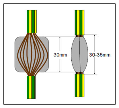
REMOVE INSULATION – 400 mm from the end of the cable, remove a 40 mm of green / yellow insulation exposing a 30–35 mm section of copper strands.
ROUGHEN – Lightly roughen 110 mm of insulation back from cut using abrasive tape.
SPREAD CONDUCTORS – At exposed section, flatten and spread out earth cable conductor strands at 30–35 mm section to allow grey sealing tape to be worked in between strands.
CUT TAPE – Cut the sealant tape to size, then position in the centre of 30–35 mm section (tape width <30 mm).
APPLY TAPE – Wrap one turn of grey sealing tape around exposed section, working it between the strands to make a watertight seal.
DO NOT STRETCH – Do not stretch sealant tape.
BUTT ENDS – Butt ends together without overlap.
REMOVE AIR GAPS – Remove any air gaps or pathways by gently pressing tape.
8.3Power and earth cables#
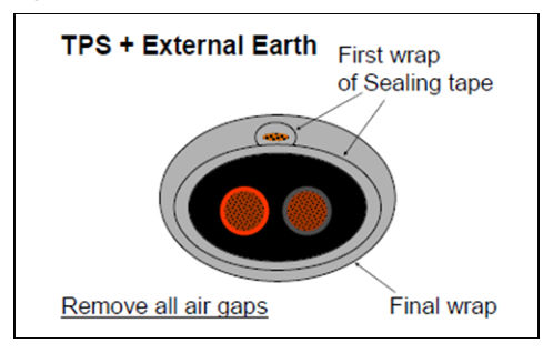
PLACE CABLES – Place the sealed sections of the earth and power cables together and press.
WRAP – One final wrap around both taking care to squeeze and smooth air paths out of taped sections.
DO NOT STRETCH – Do not stretch sealant tape.
DO NOT OVERLAP – Do not overlap ends of grey tape.