12Installation instructions – neutral joint#
12.1Remove insulation and install lugs#
REMOVE INSULATION – Remove sufficient insulation so that the copper extends fully into lug, ensuring the insulation does not extend into lug (1 mm clearance).
SELECT CRIMPING TOOL – Select correct crimping tool for secure connection.
INSTALL LUGS – Install crimp lugs onto conductor.
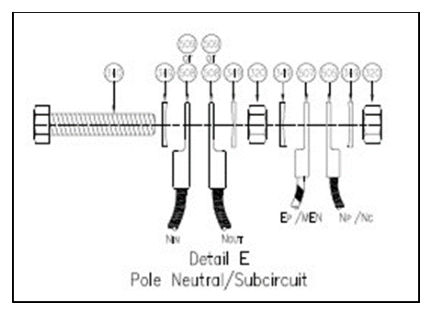
BOLTING ARRANGEMENTS – Install neutral and earth bolting arrangements required as per Standard Drawing SD1626. Use Belleville washers for spacers if required.
Note that setscrew lengths vary – see bolting details.
ARRANGE WIRING – Arrange the wiring neatly within the joint, using cable ties if necessary. Leads must run parallel for at least 40 mm to accommodate the insulating shroud.
TIGHTEN NUTS – Torque all nuts on setscrew assembly to a minimum of 20 Nm.
| Figure 12.1(a): "One hole ‘Main Earth DO NOT DISCONNECT’ warning label" was removed. |
| Figure 12.1(b) is now Figure 12.1. |
12.2Push sealing cap onto connection#
INSTALL CAP – Install cap by holding all wires and pushing the cap over the connection assembly until it goes no further.
INSTALL CLAMP – Install clamp on cap. Verify proper placement of clamp by ensuring the two pins on the bottom edge of the clamp are mated with the holes of the cap, as shown in the figure following.
APPLY PRESSURE – Apply pressure to close, using pliers if necessary. Clamp pressure points should fit into opposing grooves of cap and apply pressure between the cables.