
6.1Sensor placement for vehicle detection site#
The placement of a sensor depends upon its intended use and pavement type / characteristics. Unless otherwise specified, sensors used for vehicle detection and/or identification, must be able to measure traffic volume (counting), occupancy, speed, headway and length.
6.1.1Sensors at a signalised intersection#
Sensors at a signalised intersection can be used for traffic signal control, traffic management, for traffic survey data, or for traffic violation detection. Except for red-light camera application, a separate sensor is to be allocated for each traffic lane at signalised intersections. Where a single detector is connected to multiple traffic loops, refer to SD1426 Traffic Signals - Detector loops standard configurations for details on how the loops are connected in the pit. Sensors used in traffic signal control and management can be:
- a)stop-line or right-turn sensors at intersections
- b)slip lane sensors
- c)advance or queue sensors
- d)sensors at mid-block or school pedestrian crossings, and
- e)departure loops.
6.1.1.1Sensor selection#
Unless otherwise specified, sensors that are used to operate the traffic signal controller, as a minimum, are to measure traffic volume, headway and occupancy. This only applies to the following:
- Stop-line sensors
- Right-turn sensors
- slip lane sensors
- advance detection sensors.
6.1.1.2Stop-line sensors#
Stop-line sensors are to be located upstream of the stop-line at a signalised intersection, as shown on SD1425 Traffic Signals - Detector loops placement details.
6.1.1.3Right-turn sensors#
For the detection of right-turn vehicles, one or more sensors connected in series are to be used. Details on the placement of sensors are shown on SD1425. If required, additional sensors, are to be placed 1 m downstream from the last sensor and downstream from the stop-line.
6.1.1.4Right-turn sensor configuration#
To obtain accurate performance measures for the right-turn movement, it is highly recommended that the first sensor upstream of the stop bar be connected to a separate vehicle detector to the other sensors. The controller personality would use the 'detector diode' function to combine the sensors internally to control demand for the right-turn movement. Refer to SD1701 Traffic Signals – Detector loops counting / right turn loops and diode connection details.
For installations where there are spare detector sensor inputs in the controller, all sensors may be separated into individual detectors and the 'detector diode' function in the personality may be used to combine these sensors internally to control demand for the right-turn movement. This allows the individual sensors to be monitored and faults to be promptly detected.
Combined red-light and speed camera loops can be installed at the same approach.
Where there is a conflict between the placement of combined red-light and speed camera loops and traffic signal loops, the latter shall take preference.
6.1.1.5Mid-block crossing sensors#
Vehicle detection sensors used in mid-block (or school) pedestrian crossings are to be placed upstream of the stop-line as shown on SD1425.
6.1.1.6Advance detection sensors#
Advance detection sensors are strategically located upstream of the stop-line well in advance to measure headways (the time period between successive sensor actuations), or gap time, to terminate the traffic signal phase earlier under free flow conditions.
Advance detection sensors are to be used when approach speed is high or when there is a large proportion of heavy vehicles. They are to be located to suit the required stopping distance for the 85th percentile approach speed, at 35 metres (for 50 km/h speed limit) to 40 metres (60 km/h) upstream of the stop-line.
6.1.1.7Mid-block measurement sensors#
Mid-block measurement sensors are installed to measure traffic flow characteristics between intersections. These sensors are to be located between one third and halfway from the depart side of one intersection to the stop-line of the next downstream intersection.
6.1.1.8Depart-side sensors#
In the absence of mid-block measurement sensors, depart-side sensors are installed to determine turning volumes of shared lanes and to detect downstream link congestion. These sensors are to be located downstream of the stop-line, past the shared centre area of an intersection.
6.1.1.9Red-light camera sensors#
Traffic violation sensors are installed in conjunction with a red-light camera and flash unit, to enable red-light traffic violations to be detected and photographed. Sensors are installed in exclusive through-lanes and shared lanes where there is no left or right-turn green arrow displayed in conjunction with the full red signal.
Loops constructed for enforcement purposes must not impede normal operation of traffic signals by relocating traffic signal loops to undesirable locations. Where there is a conflict between the placement of combined red-light and speed camera loops and traffic signal loops, the latter shall take precedence.
6.1.1.9.1Red-light camera sensor placement and configuration#
Red-light camera (traffic violation) installations shall use inductive loops. The placement and configuration of these loops are as shown on both SD1425 Traffic Signals - Detector loops placement details and SD1702 Traffic Signals - Detector loops motorways management placement details. Red-light camera loops shall be:
- a)installed with edges parallel to both the stop-line and approach / departure kerb, where the stop-line is not perpendicular to the kerb, the shape of the loop shall be a parallelogram, and
- b)installed so that no part of the loop shall be any closer than 1.2 m to the trajectory of cross or turning traffic of another phase. This will prevent false actuations.
For intersections that are connected to STREAMS, it is recommended that detector 16 be connected to the camera unit so that camera alarms, such as no film, camera faults, and so on, can be reported to STREAMS. Therefore, detector 16 should not be used as a normal detector when a red-light camera is installed at such an intersection. Note that controller software version 2.4 or later allows for the status of up to 24 vehicle detectors to be returned to STREAMS, so detector 24 may be used for this purpose where this software is installed.
6.1.1.10Bicycle sensors#
Bicycle sensors are to be installed within bicycle lanes / paths only. These sensors are to be placed upstream of the stop-line. Where inductive loop is used for detecting bicycles, the centre of the loop is to be marked longitudinally with 5 diamonds 100 mm x 100 mm at 300 mm centres) as shown on SD1425.
6.1.2Motorway detection sensors#
Motorway detection sensors refer to sensors located either on the motorway, entry-ramps or exit-ramps. These vehicle detection sensors are used to increase the safety and performance of the road network through incident detection and management, ramp signalling and determining traveller information. For additional information, refer to SD1702 Traffic Signals - Detector loops motorways management placement details.
6.1.2.1On motorways#
Vehicle detection sensors on motorways are to be located as follows:
- 1.immediately upstream from an entry-ramp nose
- 2.immediately downstream from an exit-ramp nose, and
- 3.at 500 m maximum spacing.
Designers should refer to Queensland Guide to Smart Motorways (QGSM).
6.1.2.2Ramp signalling#
The department’s ramp signalling model is based on ramp signalling algorithms.
There are 4 different types of entry-ramps supported by this model as described below:
- Simple entry-ramp types
- – this type of entry-ramp involves a simple ramp of one or more general traffic lanes where the stop bar extends across ALL lanes of the entry-ramp, and
- Complex entry-ramp types
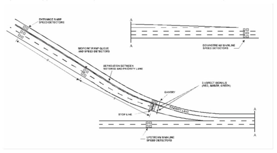
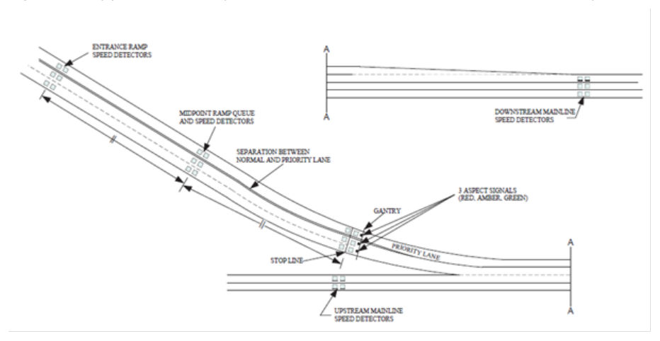
- – two lanes of metered traffic, plus a priority lane
- – two lanes of metered traffic, plus a metered priority lane, and
- – motorway to motorway entry-ramps.
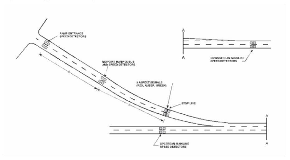
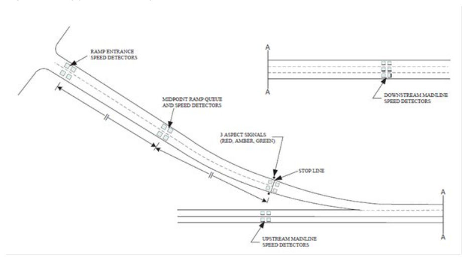
Designers must consult with the department’s Active Network Operations unit when placing sensors for complex ramp signalling. Refer to QGTM Part 9 Section 8 for further details. The ramp signalling algorithms require vehicle detection sensors to be placed at various locations to optimise motorway flow. The required locations are described in Figures 6.1.2.2(a) to 6.1.2.2(d), and Section 6.1.2.2.1.
6.1.2.2.1Sensor placement and configuration#
Unless otherwise specified, all sensors used for the purpose of ramp signalling, shall permit measurement of traffic volume (counting), speed, headway, occupancy and vehicle length.
Main line sensors#
The sensors on the mainline provide the data required for the ramp signalling algorithms to ensure the ramps are metered appropriately to optimise the motorway flow. These sensors are to be placed outside the merging area as follows:
- upstream mainline sensors are to be placed before the ramp nose, and
- downstream mainline sensors are to be placed at the end of the final merge taper, or
- downstream mainline sensors are to be placed at minimum of 320 m from the ramp nose for entry-ramps with a single added lane situation without a merge.
The upstream mainline sensors are used for traffic counting and monitoring motorway performance. These sensors can also be used by the ramp signalling algorithm as a backup if the downstream mainline sensors become unavailable for any reason.
These mainline sensors shall form part of the regular array of mainline vehicle sensors.
Stop line sensors#
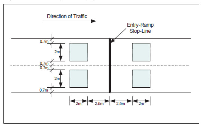
Sensors are to be placed immediately upstream of the stop-line to enable cycling of the ramp signals when the ramp signalling system is active.
Sensors are also to be placed immediately downstream of the stop-line for vehicle counting associated with the ramp signalling algorithms.
When inductive loops are used as sensors, they are to be placed as follows:
- loop to be placed 2.5 metres (trailing edge of loop) upstream of the stop-line, and
- loop to be placed 2.5 metres (leading edge of loop) downstream of the stop-line.
Ramp queue sensors#
Sensors are to be placed at the ramp entrance and at the midpoint between the stop-line and the start of the ramp for queue length estimates and queue management by the ramp signalling algorithms.
Midpoint sensors are not required for an unmetered priority access lane; however, it is recommended that midpoint sensors be installed on unmetered priority access lanes for future consideration.
Where a ramp is very short relative to the desirable storage, additional sensors may be required to detect queues on the arterial roads leading on to the ramp.
6.1.2.2.2Motorway-to-motorway entry-ramps#
Motorway-to-motorway ramps provide connections between high-speed facilities where drivers may not expect to stop, nor expect to encounter a queue of stopped vehicles. Therefore, signalling motorway-to-motorway entry-ramps should be avoided wherever practicable. When this is not possible, adequate storage should be catered for in the geometric design of these ramps. The principles mentioned in Section 6.2.2.1 shall be applied on these ramps for effective ramp signalling.
6.1.2.2.3Non-metered entry-ramps#
Where ramp metering is not specified, the entry-ramps must have their flow measured for traffic volume (counting), speed, headway, occupancy and vehicle length. The sensors required to measure these parameters are to be located adjacent to the sensors measuring the mainline motorway flow immediately upstream of the entry-ramp nose.
6.1.2.2.4Exit-ramps#
All exit-ramps must have their flow measured for traffic volume (counting), speed, headway, occupancy and vehicle length. The sensors required to measure these parameters are to be located adjacent to the sensors measuring the mainline motorway flow towards the start of the exit-ramp so that queues can be detected and prevented from extending on to the motorway. Typically, these vehicle detection sensors are located at the one-third point along the ramp measured from the gore area. This may be adjusted depending on the situation.