9.3Sensor placement at active transport site#
Active transport counter and classifier (ATCC) sites may use pneumatic tube, piezoelectric sensor, PIR sensor, and video analytics cameras as detailed in the table below. The following sections discuss the placement of these sensors for various applications.
| Sensing technology | Targets | Remarks |
|---|---|---|
| pneumatic tube | bicycle, scooter | • suit temporary site only as not requiring pavement cutting, and • unable to differentiate bicycle and scooter |
| piezoelectric sensor | bicycle, scooter | • requires pavement cutting, and • unable to differentiate bicycle and scooter |
| PIR sensor | pedestrian | • animals could be mistaken as pedestrians |
| video analytics camera | bicycle, scooter, pedestrian, undetermined object | • site specific AI training is required |
9.3.1Bicycle counter#
A typical cycle path is a 3 m wide (between edge lines) single carriageway corridor for bi-directional cycling traffic movement. To construct a bicycle counter, a pair of piezoelectric sensors are installed across the path from one edge line to the edge line on the opposite side, perpendicular to the centre line. Spacing between the piezoelectric sensors shall be 300 mm. This configuration enables the counting of bicycles in each of the travelling directions. For dimensions and other details, refer to SD1928 ITS – Bicycle counter.
A piezoelectric sensor-based bicycle counter is unable to differentiate bicycle, scooter, and any 2-axle personal mobility device, though axle spacing parameter can be calculated. Data reported from a site of this kind is the count of all bicycle-like traffic.
Figure 9.3.1 exhibits a typical Piezo-Piezo bicycle counter configuration. For non-permanent bicycle counting site, pneumatic tubes may be installed in lieu of piezoelectric sensors.
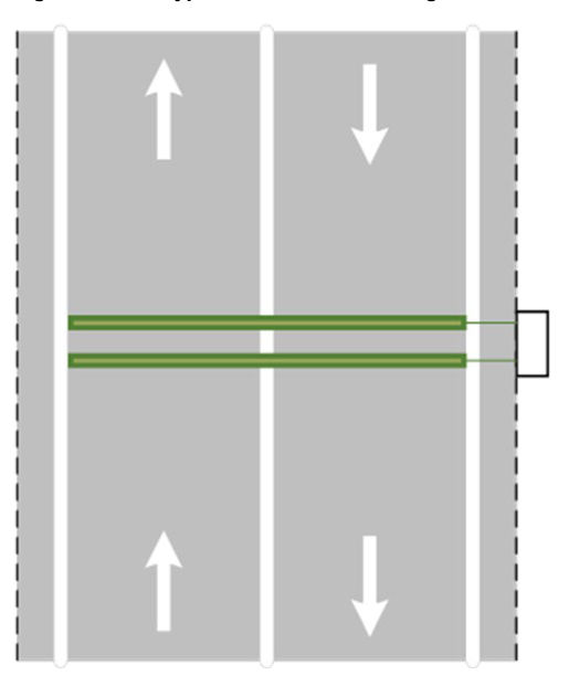
For heavy traffic sites, the designer should consider having a pair of piezoelectric sensors on each lane of the path, to reduce the probability of having multiple cyclists concurrently rolling over the same piezoelectric sensor causing errors in detection.
9.3.2Collocated bicycle and pedestrian counter#
Pedestrian counters use passive infrared (PIR) sensing technology to detect the presence of an object which has a differentiable temperature signature against the background.
A pedestrian counter can be installed in the form of a combined bicycle and pedestrian counting unit at site where both pedestrian and bicycle counts are needed, though it can be standalone.
On a shared path, a combined bicycle and pedestrian counting unit collects bicycle and pedestrian counts. The PIR sensor shall be mounted above the centre line of the path to create a detection zone to cover the pedestrian and cyclist traffic in both directions. The PIR sensor shall be placed right above the piezo-piezo bicycle sensors. In this setup, the combined bicycle and pedestrian counting unit should accurately report the true count of pedestrians by excluding cyclists who are also detected by the PIR sensor. For dimensions and placement details of the PIR sensor refer to SD1929 ITS – Bicycle and pedestrian counter.
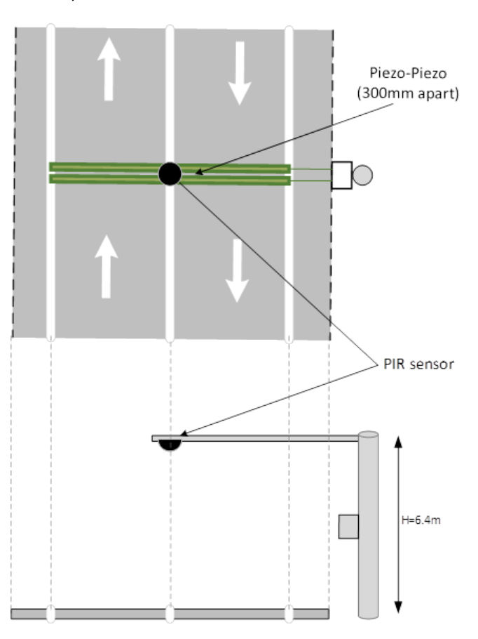
In sites where cyclist and pedestrian lanes are separated physically, the combined bicycle / pedestrian counting unit can be used as 2 independent counters, that is, one for bicycle counting and one for pedestrian counting.
9.3.3Active transport classifier#
Video analytics (VA) camera is used to classify active transport path users captured in video image frames. With pre-trained machine learning algorithms and site-specific enhancement learning, the camera can detect and identify bicycle, scooter, pedestrian or undetermined. A VA camera can be further extended to identify a wider range of active transport modes travelling on cycle path and footpath after its algorithms have been properly trained.
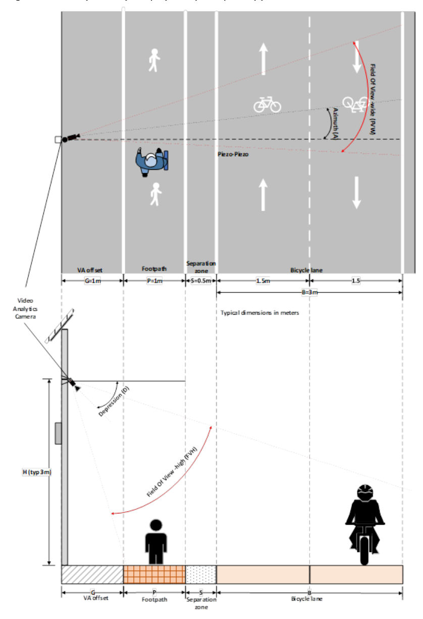
Active transport classifier can be installed on either shared path or separated path configuration. Figure 9.3.3 show a plan view and section view respectively of a typical site where cycle path and footpath are separated.
9.3.3.1Design parameters#
Designing an active transport classification site with VA cameras requires the designer to optimise a set of design parameters discussed in the following sub-sections, to achieve a best detection result. Design parameters can be grouped under 5 categories, namely:
- Site geometry (Section 9.3.3.1.1)
- Path user attributes (Section 9.3.3.1.2)
- Detection zones (Section 9.3.3.1.3)
- VA camera placement (Section 9.3.3.1.4), and
- Camera type and associated features (Section 9.3.3.1.5).
9.3.3.1.1Site geometry#
The general requirements for the detection of active travel defined in Section 9.1 apply to the selection of site for video analytics (VA). Site geometry shall be evaluated for suitability for VA prior to selection. Geometric parameters considered for VA installation include:
- camera Offset
- footpath width
- separation zone width, where applicable
- bicycle lane width
- path curvature, where applicable, and
- longitudinal slope of path.
9.3.3.1.2Path user attributes#
The designer should make the following assumptions regarding prospective path users, including pedestrians, scooter riders, and cyclists, under normal conditions:
- Maximum height of pedestrians, scooter riders, and cyclists (when seated on bicycles) is 1.75 m.
- Typical horizontal width for a pedestrian is 0.4 m.
- Typical horizontal width for a bicycle is 2 m.
- Cyclists generally avoid riding closer than 300 mm to the path edge when possible.
- Pedestrians tend to walk in the centre of the footpath if available. On a shared path, pedestrians keep to the left.
- Typical pedestrian speed is 4 kph, with a maximum speed of 16 kph.
- Typical cyclist speed is 20 kph, with a maximum speed of 40 kph.
9.3.3.1.3Detection zone#
The detection zone is the area on the path where the VA camera has a full view of the entire path user, including any mobility device where present. It excludes the areas where only part of the path user is visible, and regions outside the path.
Whether on a shared path or separate path, the detection zone(s) should encompass pedestrians on the footpath and cyclists in both near and far cycle lane. The detection zone should generally meet the following criteria:
- The line of sight between the camera and its detection zone(s) must be unobstructed.
- The physical path area within the operating zone must be long enough for path users to traverse, allowing the VA camera sufficient time to capture the required image frames. The length of the path requirement is dependent of the features of the camera used (refer to Sections 9.3.3.1.4 and 9.3.3.1.5 below).
- The straight-line distance between the VA camera and any path user on the detection zone(s) should not exceed 30 m to avoid capturing objects too small to recognise.
9.3.3.1.4VA Camera placement#
The VA camera's setup parameters define the operating areas where it detects and classifies path users; these areas should be configured for maximum coverage. General requirements for the placement of VA camera include:
- The VA camera must have a clear view of the entire bicycle, scooter, and pedestrian within the detection zone to accurately determine their presence.
- The VA camera should be oriented away from sun glare or any other direct light sources that could interfere with its functionality.
- Fine-tuning during installation, commissioning, and maintenance maybe required for optimal performance. If the mounting kit allows, the installer may rotate the camera about the viewing axis to optimise the field of view. Any adjustments to design parameters must be documented to support future maintenance activities.
The below define the considerations in defining key parameters in VA camera placement:
- Location and Mounting height
- The VA camera should be mounted on the side closer to the footpath than to the cycle path as pedestrians generally travel slower than cyclists. This arrangement provides a longer detection distance for bicycles and reduces the risk by placing the mounting structure away from the higher-speed cycling path.
- Avoid placing the VA camera in areas between the footpath and cycle path where the side view of the path user is minimal.
- Installing the VA camera on a pole set farther from the path, can extend the detection zone coverage, though increased distance may reduce object size in images.
- The VA camera shall be mounted at height to minimise vandalism while providing a clear view of users moving side-by-side. However, placing the VA camera too high may reduce image quality due to potential vibration and increased physical distance. A mounting height between 3.0 m and 6.5 m is recommended.
Depression#
- Orientating the VA camera along the path's longitudinal axis, extends the length of the detection zone. However, aligning the VA camera more longitudinally, however, reduces the ability to distinguish between different kinds of path users, for example, pedestrian versus scooter rider. The distance between the detection zone and the camera becomes longer if the depression angle remains unchanged. A longer distance equates smaller object size in the image.
- Marking a control point on the ground can assist installers aim the VA camera accurately during setup. The design plan should include the coordinates of the control point.
- In general, the depression angle, D, should not exceed 75°.
Azimuth#
- The VA camera should be aligned towards the side view of the objects as much as possible to distinguish between bicycles and scooters, with azimuth angle as close to 0° as possible.
- The azimuth angle of VA camera should not exceed 60° to ensure sufficient side view of an object to be viewed.
9.3.3.1.5VA camera type and features#
The type of VA camera used influences the target field of view (FoV) and the detection zone. A good VA camera may compensate for unfavourable site geometry resulting in optimal detection zone. The main considerations for a VA camera include:
- Frame rate (fps) – a minimum video frame rate 25 fps (frames per second)
- Focal length (mm) – The focal length of a camera is a major factor affecting the field of view
- Camera lens format – In selecting lens, the field of view of the camera shall be wide enough to create an optimal detection zone. However, wide angle lens incurs distortion that may cause complication for algorithms to identify the path user. For a given focal length, the field of view varies depending on the camera lens.
- Resolution – The target resolution for an image of a path user in a frame shall be 64 x 48 pixels or better. An image with more pixels makes it easier to distinguish between types, such as, cyclist, scooter rider, and pedestrian.
- Night vision – minimum level of illumination that the camera can adequately perform VA functions.
Table 9.3.3.1 lists the site design parameters applicable to a separated path configuration, using Figure 9.3.3 as a design reference plan. On a shared path, where pedestrians and cyclists share the same path, footpath width and cycle path-footpath separation parameters can be set to zero. Refer to Section 9.3.3.3.
9.3.3.2Placement parameters on separated path#
Where cycle path and footpath are separated, the VA camera shall be placed on the footpath side to provide longer camera exposure distance for bicycles and scooters which travel faster than pedestrians.
Figure 9.3.3 shows a model arrangement for an Active Transport classification site on separated footpath / cycle path environment.
| Category | Parameter description | Parameter symbol (unit) | Range of Values | Typical Design Value (Example) | Remarks |
|---|---|---|---|---|---|
| Site Geometry | Camera offset from path | G (m) | 0.5-2.0 | 1 | Offset of the VA camera from nearest path edge (Refer to Figure 9.3.3) |
| Footpath lane width | P (m) | 0.5-2.0 | 1.5 | Pedestrians are assumed travelling in the middle of the footpath. (Refer to Figure 9.3.3) | |
| Bicycle / footpath lane Separation | S (m) | 0.5-1.0 | 0.5 | Assume separated paths, that is, pedestrians are not allowed in cycle path. (Refer to Figure 9.3.3) | |
| Bicycle path lane width | B (m) | 3.0-5.0 | 3 | Path is assumed to be 2-lane bi-directional, and cyclists observe proper lane discipline by travelling in the middle of the corresponding lane. (Refer to Figure 9.3.3) | |
| Cycle path horizontal curvature radius | R (m) | >0 for camera outside the curve <0 for camera inside the curve ∞ for camera on straight path | ∞ | Refer to Section 9.3.3.4 for illustrations of VA camera location relative to curvature. | |
| Path longitudinal slope (gradient) | SL (%) | 0% (flat) – otherwise 3% (1:33) - 5% (1:20) | 0 | Must not exceed 5% |
| Category | Parameter description | Parameter symbol (unit) | Range of Values | Typical Design Value (Example) | Remarks |
|---|---|---|---|---|---|
| Path User attributes | Path user height (Pedestrians and cyclists) | (m) | 1.0-2.0 | 1.75 | Path user vertical height |
| Pedestrian speed (includes running) | VP (m/s) | 0.8-4.5 | 1 | Typical walking speed is 1 m/s. Jogging speed, in some locations, may be as fast as 4.5 m/s. | |
| Bicycle / scooter speed | VB (m/s) or km/h | 5-12.5 (18 km/h – 45 km/h) | 8 (~30 km/h) | Avoid location where travel speed beyond 11.1 m/s (40 km/h) | |
| Detection Zone * | Footpath coverage (effective footpath length in view) | CP (m) | 0.5-4 | 0.81 | The effective path length in which a typical pedestrian (1.75 m) walking in the middle of the footpath are seen in view. Path length requirement depends on camera performance. |
| Near cycle lane coverage (effective near cycle lane length in view) | CBN (m) | 3.0-10.0 | 5.56 | The effective path length in which cyclists 1.75 m in height riding 300 mm offset from their left edge line in the near cycle lane are seen in view. Path length requirement depends on camera performance. | |
| Far cycle lane coverage (effective far cycle lane length in view) | CBF (m) | 3.0-10.0 | 8.88 | The effective path length in which cyclists 1.75 m in height riding 300 mm offset from their left edge line in the far cycle lane are seen in view. Path length requirement depends on camera performance. | |
| VA Camera Placement | Azimuth angle (from camera toward cycle path) | A (°) | -60° to 60° | 30 | The camera Pan range - (Pan Angle) |
| Depression angle | D (°) | 15° to 75° | 30 | The camera vertical tilt range | |
| Camera offset from path | G (m) | 0.5-2.0 | 1 | Offset of the VA camera from nearest path edge (Refer to Figure 9.3.3) | |
| Mounting height | H (m) | 3.0 - 6.5 | 3 | Mounting height of VA camera up the pole | |
| Control point coordinate offset from VA pole | C lat (m), C lon (m) | 2.0 - 10.0 | 4.5, 2.6 | A point on site floor to aid aligning camera, measured as lateral and longitudinal offsets from camera pole along the path respectively. | |
| Camera Features | Field of view (width x height) | FVW (°) x FVH (°) | Any range of values that capture the detection zone | 65.4 x 46.4 | The horizontal and vertical angles determining the field of view for the VA camera. (Refer to Figure 9.3.3) |
| Frame rate | FR (fps) | >=25 fps | 25 | Minimum departmental requirement for frame rates in frames per second (fps) |
9.3.3.3Placement parameters on shared path#
On a shared path where cyclists, scooter riders and pedestrians share the same physical space, the VA camera shall be placed on the side that provides the best visual quality. Generally, the side having minimum amount of sun glare is preferred.
Other factors to consider when selecting the optimal location to install VA camera include level of risk of vandalism and availability of sufficient solar-generated power.
The model depicted by Figure 9.3.3 can represent a site on shared path by setting the 2 parameters, Footpath separation (S) and Footpath width (P), to zero.
9.3.3.4Site on curve path#
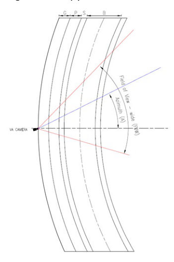
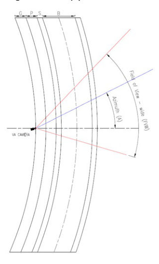
It is advisable to install a VA camera on a straight path. However, if a site must be installed on a curvy path, then the horizontal curvature radius of the path is recommended to be greater than 10 times the distance from the VA camera pole to the median of the cycle path.
Installing a VA camera on the outside of a curvy path is equivalent to increasing the azimuth angle reducing the side view to the object. Refer to Figure 9.3.3.4(a). Whereas if a VA camera is installed in the inside of a curve, the detection zone is shortened compared to a straight path. Refer to Figure 9.3.3.4(b).