7.4.3Inductive loop installation#
Inductive loop installation for traffic counter / classifier applications shall be as described in Section 6.2.2, except as varied following.
Only 2 m x 2 m square loops shall be used for traffic counter / classifier. Each loop shall have 4 turns (or 5 turns, depending on feeder cable length) to achieve the following electrical characteristics as measured across its input terminals in the cabinet:
- Inductance: 100 µH to 250 µH
- Resistance: ≤ 2.5 Ω
- Q factor: ~20 at 40 kHz
The applicable Standard Drawings for counter / classifier installation are as listed following:
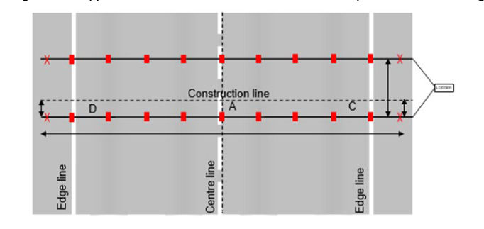
- SD1916 ITS – Axle-based vehicle classifier sensor installation details
- SD1917 ITS – Axle-based vehicle classifier sensor configuration Loop-Piezo-Loop
- SD1918 ITS – Axle-based vehicle classifier sensor configuration Piezo-Loop-Piezo, and
- SD1920 ITS – Length based vehicle classifier sensor configuration Loop-Loop.