7.4.4Piezoelectric sensor installation#
7.4.4.1Scope#
Piezoelectric sensors are commonly used for vehicle classification and weigh-in-motion applications.
Brass Linguini piezoelectric sensors, which are the predominant piezoelectric sensors used by the department, come in 2 types, based on their output uniformity. The type with uniformity factor of ± 7% or better is suitable for use in counters / classifiers for axle detection and in weigh-in-motion installations for weighing axle loads, whereas the type with uniformity factor worse than ± 7%, typically ± 20%, can only be used in counters / classifiers for axle detection.
The following installation procedures apply only to the piezoelectric sensor of dimensions 1.5 mm thick and 6.5 mm wide. For installation procedures of piezoelectric sensors of different dimensions or sensors other than this technology, for example, quartz crystal sensor, refer to the manufacturers' instructions.
Where Piezo sensors are to be installed into an Open Graded Asphalt (OGA) surface, this shall be done in accordance with the key considerations listed in Section 7.4.4.3.
7.4.4.2Installation procedure#
A Brass Linguini piezoelectric sensor is designed for permanent installation into a straight slot on the road surface across the traffic lane in a flexible format so that it can conform to the profile of the road. The dimensions of the slot cut in the road shall comply with this instruction to minimise the impact on the road's structural integrity. The final installation shall be ideally flush with the road surface. Up to 1 mm protrusion is also acceptable; however, no dip is allowed. In most applications, the piezoelectric sensor life expectancy exceeds that of pavement.
Installation procedures are as follows:
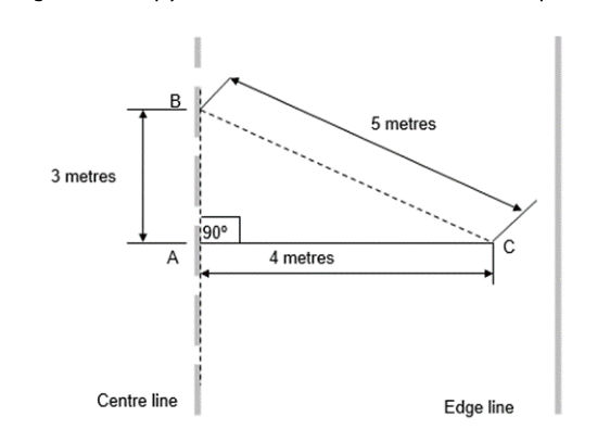
- 1.Mark the location of the first piezo slot at a point in the centre of the road. This will be point A (refer to Figure 7.4.4.2(a)).
- 2.To ensure the piezo slot is marked exactly perpendicular to the traffic lane, draw a 3 m straight line along the centre line of the road with chalk on either side of point A.
- 3.Use the 3-4-5 rule (Pythagoras' Theorem) to project a line (AC) perpendicular to the chalk line.
- 4.Mark out the length of the piezo slot. Verify that the feeder cable length is enough to reach the cabinet.
- 5.Dry cut the sensor slot using a 19 mm thick (or a stack of multiple thinner blades to form a 19 mm thick) Diamond Blade. The slot must be 19 mm wide ± 1 mm by a minimum of 25 mm deep. Cut the slot 200 mm longer than the sensor length to accommodate sensor tail or feeder. The direction of cutting should be from the Edge line towards the Centre line of road. This will make it easier for the operator to maintain a uniform depth of slot without adjusting the height of the blade to compensate for change in grade of road.
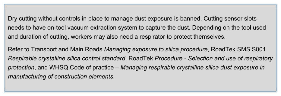
Dry cutting without controls in place to manage dust exposure is banned. Cutting sensor slots needs to have on-tool vacuum extraction system to capture the dust. Depending on the tool used and duration of cutting, workers may also need a respirator to protect themselves.
Refer to Transport and Main Roads Managing exposure to silica procedure, RoadTek SMS S001 Respirable crystalline silica control standard, RoadTek Procedure - Selection and use of respiratory protection, and WHSQ Code of practice – Managing respirable crystalline silica dust exposure in manufacturing of construction elements.
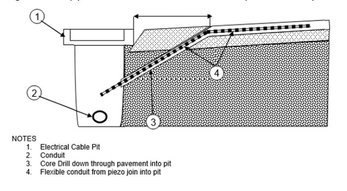
- 6.Cut feeder run slots at 19 mm width. Centre the feeder slot on the sensor slot. Feeder slots are typically cut to a depth of 25 mm stopping 300 mm in from road edge. With a 25 mm core drill bit, drill down through pavement into pit. Before removing the core drill, place 20 mm flexible electrical conduit up the inside drill. Remove the core drill and the conduit will be installed. This method ensures that the cable is protected in its transition from road to pit (refer to Figure 7.4.4.2(b)).
- 7.Vacuum-clean all slots to ensure they are free of dust or debris, and then dry all slots with compressed air and/or gas burners.
- 8.Remove sensor from packaging. Visually inspect sensor to ensure it is straight without any twists or curls. Check feeder cable for bare wire. Check joint for cracks or gaps. Sensors having any of these issues shall not be used. Refer to the QC test data sheet (enclosed inside the package) to ensure the correct sensor is to be installed. Verify that there is sufficient feeder cable with intact insulation to reach the cabinet.
- 9.Measure capacitance, dissipation factor and insulation of the sensor. Capacitance and dissipation should be within ± 20% of the enclosed data sheet. Resistance should be infinite when measured using an ohmmeter with a 20 MΩ range setting. Record the result of the measurements.
- 10.Place sensor next to the slot. From this point forward, handle the sensor with latex (or equivalent) gloves.
- 11.Clean sensor with steel wool or emery pad. Wipe down with alcohol and clean lint free cloth.
- 12.Place installation brackets on sensor every 150 mm for the length of the sensor. Use the 20 mm (small) brackets supplied together with the sensor. Thread feeder cable through flexible conduit.
- 13.Place sensor in the sensor slot. The end of the sensor should be at least 50 mm from the end of the slot, and the tip shall not touch the bottom of the slot. The lead attachment or joint shall not touch the bottom or the sides of the slot.
- 14.If any of the 3/4” 20 mm (small) brackets do not fit snugly against the sides of the slot or are loose, replace with a 25 mm (large) bracket and repeat Step 13.
- 15.Starting at the non-lead end, use the installation depth gauge to position the sensor so that it is 9 mm below the surface of the road by pressing the depth gauge against the top of the sensor. At this point, the installation bracket is 3 mm below the surface of the road.
- 16.Visually inspect the length of the sensor to ensure it is at uniform depth along its length and it is level and not twisted.
- 17.Run the feeder wire the length of the feeder slot (refer to Figure 7.4.2.2(c)).
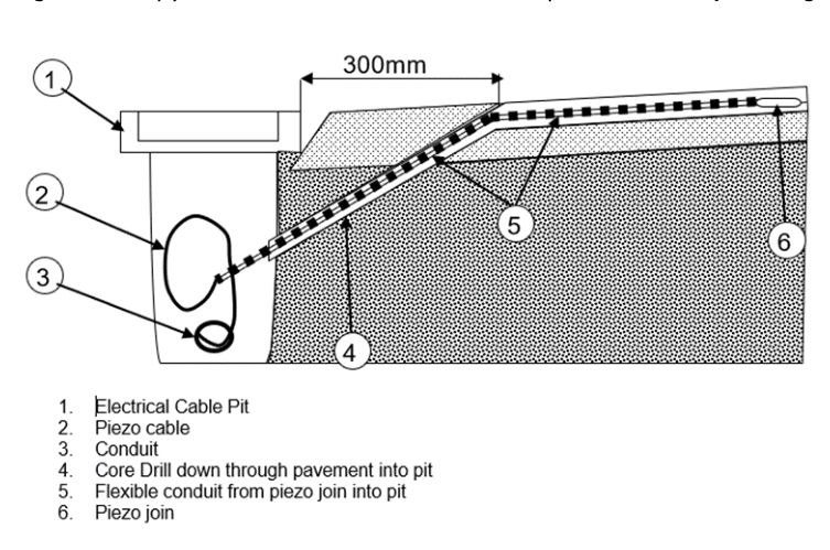
- 18.Seal conduit and feeder cable with a sealant to prevent epoxy running down into pit.
- 19.Place 50 mm masking tape along the length of both sides of the sensor slot. Tape must be 2 mm away from the slot.
- 20.Place another 50 mm masking tape along the length of the first row of tape ensuring a 5-10 mm overlap. This will allow excess epoxy to be removed easily (refer to Figure 7.4.4.2(d)).
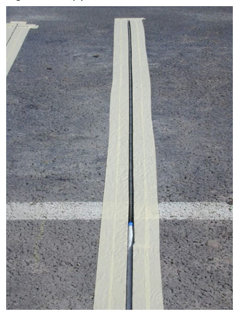
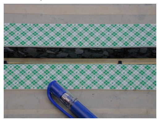
- 21.Adhere double sided tape on top of the first row of masking tape on both sides, ensuring 2 mm away from the slot. Do not remove paper covering the adhesive. This provides a 2-3 mm formwork above the road surface level. When the slot is filled with epoxy to the level of the double-sided tape, it ensures that epoxy is 2-3 mm proud of the road surface (refer to Figure 7.4.4.2(e)).
- 22.Using low speed mixing drill (450 rpm) and a mixing paddle, premix both parts of the epoxy as per manufacturer's instructions.
- 23.Add hardener to epoxy and mix according to manufacturer’s instructions.
- 24.Immediately pour epoxy into the slot using a small bead. Using a small bead allows the installer to watch the epoxy flow under the sensor, eliminating air pockets. Start at the end and pour towards the lead attachment. Repeat until slot is overflowing the level of the double-sided tape slightly.
- 25.Using putty knife, start at the lead attachment and lightly screed towards the end of the Piezo ensuring in that there is enough epoxy to keep a uniformed height along the length of the slot (refer to Figure 7.4.4.2(f)).
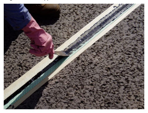
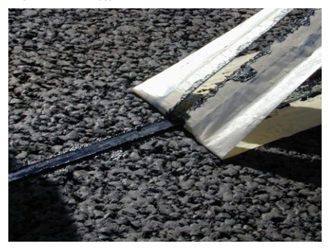
- 26.Remove tape as soon as epoxy begins to set (2-5 min) (refer to Figure 7.4.4.2(g).
- 27.Once epoxy is cured, use a belt sander to sand the top of the epoxy. For WiM sensors, the epoxy finish should be flush or no more than + 1 mm proud of roads surface. For classifier sensors, the epoxy finish should be 1 mm to 2 mm proud of roads surface. Regardless of finish epoxy height, it must be uniform height along the sensor length. If the epoxy finish is low anywhere along its length, it must be topped up with additional epoxy (refer to Figure 7.4.4.2(h)).
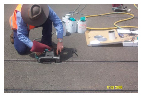
Wait allotted period, as prescribed in the material datasheet, to allow epoxy to fully cure and then open the lane to traffic.
Connect an oscilloscope to sensors and view wave forms as vehicles pass. Ensure signal is clear without noise.
7.4.4.3Installation of piezoelectric sensor on Open Grade Asphalt (OGA) pavement#
Open Graded Asphalt (OGA) is often specified for the road surface on high-speed, multi-lane roads such as freeways, highways, and heavily trafficked urban roads. It is different to other asphalt mix types, as it is designed to be permeable and allow for surface water to drain vertically through the OGA layer to an impermeable waterproofing seal and then laterally to the edge of the pavement. It is very important that an outlet be provided for the water that enters an OGA, otherwise, the layer deteriorates due to the ongoing presence of moisture in the layer. For this reason, OGA must have a free draining edge and be placed above the lip level of any adjacent kerb and channel. OGA contains a large proportion of coarse aggregate and only a small amount of fine aggregate, resulting in a high interconnected void content between 20-25%, which makes the asphalt highly permeable. This in turn reduces the risk of vehicles aquaplaning in wet weather, due to the rapid removal of water from the surfacing. Another safety benefit is a reduction in water spray which results in improved visibility in wet weather. OGA has also been used in areas where a reduction in tyre road noise generation is required, as it has a high negative texture. The nominal size of the aggregate used for OGA is either 10 mm or 14 mm and generally placed at a thickness of approximately three times the nominal aggregate size (refer to Technical Specification MRTS30 Asphalt Pavements for layer thickness requirements). Due to its composition and high air voids content, OGA has a shorter life expectancy than dense graded asphalt and does not perform as well in areas where high shear forces can be expected, such as heavily trafficked intersections.
The installation of piezo sensors into asphalt wearing course, as shown on departmental SD1906 ITS - WIM Piezo Sensor Installation Details, requires a 19 mm wide x 25 mm deep slot be cut into the surfacing. A polyurethane suitable epoxy resin sealant is then used to fill the slot to protect the wires, it is important that only departmental approved products are used in the construction and maintenance of infrastructure projects.
Piezo sensors are installed in pavement at locations where Austroads 12 bin vehicle classification data is required. Brass piezo sensors may be installed in OGA, however precautions are to be applied to ensure installations are not problematic due to several reasons.
Firstly, as OGA is porous, it is critical that the layer remains free draining. If the drainage path is blocked within the asphalt layer, the asphalt mix can remain in a moist condition state well after rainfall ceases. The long-term presence of moisture within the layer will typically lead to premature stripping and ravelling of the asphalt. To minimise this risk, it is important that the depth of cut be limited to 25 mm.
Secondly, where Piezo sensors are to be installed into an OGA surface, it is important that designers carefully consider the impact that the installation will have on the drainage properties of OGA. Given this, it is important that these piezo sensors are installed in locations where the road surface drainage paths are relatively short, and the design water film depth is below the desirable limit. Conversely, installing piezo sensors in locations where the road surface drainage paths are relatively long and/or the design water film depth is above the desirable limit, should be avoided.
Lastly, any saw cuts in an asphalt surfacing will represent a point of weakness. This weakness will be more pronounced in an OGA surfacing (when compared to other asphalt types) and may be more prone to premature ravelling / potholing in the longer term. Departmental experience is that, when polyurethane epoxy resin fillers are used, premature pavement failure has not occurred.
Where inductive loops are installed in conjunction with piezo sensors in new pavements, for best pavement performance, preformed loops are to be used, installed below the wearing layer in accordance with departmental SD1424 Traffic Signals – Detector Loops Installation Details.
To ensure optimum performance of both the pavement and the sensors, brass piezos shall be cut into OGA under the following conditions:
- Piezo slot depth is not to exceed 25 mm
- Piezo sensors are not to be installed on vertical curves
- Piezo sensors are not to be installed on longitudinal grades exceeding ± 2%
- Piezo sensors are only to be installed in pavements with a - 3% crossfall, and
- Piezo slot to be sealed with polyurethane epoxy resin in accordance with the departmental standard drawing.