
8Placement and installation of high-speed weigh-in-motion sensors#
A WiM site requires a combination of inductive loops, piezoelectric sensors and/or strain gauges.
The function of inductive loops is to detect the presence of a vehicle. Vehicle length parameter can be estimated with the speed and duration of the vehicles being detected. Inductive loops used in WiM sites shall be of the same characteristics used in classifier / counter placement detailed in Section 7.4.3.
Brass Linguini piezoelectric sensors come in multiple grades, based on their output uniformity. The piezoelectric sensors for weighing function shall have a uniformity factor of ± 7% or better as a minimum requirement. A pair of piezoelectric sensors of constant spacing in a WiM site also allows the detection of vehicle travelling speed.
Strain gauge used in WiM sites is a machine milled steel bar of dimensions 300 mm (L) x 30 mm (W) x 6 mm (T). The central section of the bar is milled into a 30 mm diameter ring. Attached to this ring is a Wheatstone bridge and a buffer amplifier circuit which converts electrical resistance changes, caused by deflection of the gauge, to electrical current, before feeding the current signal to a data acquisition system unit.
8.1Site selection#
For the WiM system to perform properly, the Contractor shall provide and maintain an adequate operating environment for the system's sensors and instruments. Proper selection, construction, and maintenance of each WiM site, including maintenance of the sensors, are extremely important.
The following site conditions shall be provided, as a minimum, by the Contractor to consistently meet the specified performance criteria.
This applies to both new road constructions where a WiM site is specified and an existing road installation. The Contractor is responsible for any Site assessments and investigations required to satisfy the site conditions.
8.1.1Horizontal curvature#
The horizontal curvature of the roadway lane for 100 m in advance of and 50 m beyond the WiM system sensors shall have a radius not less than 1700 m measured along the centreline of the lane.
8.1.2Longitudinal gradient#
The longitudinal gradient of the road surface for 100 m in advance of and 50 m beyond the WiM system sensors shall not exceed ± 2%.
8.1.3Cross carriageway gradient#
For bi-directional single carriageways, the cross slope (lateral gradient) of the road surface for 100 m in advance of and 100 m beyond the WiM system sensors shall not exceed - 3%.
For dual carriageways, the cross slope (lateral gradient) of the road surface for 100 m in advance of and 50 m beyond the WiM system sensors shall not exceed - 3%.
8.1.4Lane width and line markings#
The width of the paved roadway for 100 m in advance of and 50 m beyond the WiM system sensors shall accommodate a sealed shoulder of minimum 1.0 m wide on each side of the road and 3.5 m per trafficable lane.
The trafficable lane is the portion of the road devoted particularly to the use of vehicles moving in a forward direction as demarcated by appropriate line markings which shall be 100 mm to 150 mm wide.
8.1.5Surface evenness#
Roadway surface evenness contributes to the accuracy of weighing vehicle axles. Table 8.1.5 provides indicative surface evenness parameters required to achieve the expected accuracy of a WiM site. Rutting is measured with a 3 m straightedge placed anywhere within a lane, whereas road roughness count is measured at 20 m intervals. These parameters apply to the paved roadway 100 m in advance of and 50 m beyond the WiM system sensors.
| Evenness parameters | Single axle weighing accuracy (95% confidence level) ± 15% | Single axle weighing accuracy (95% confidence level) ± 20% | Single axle weighing accuracy (95% confidence level) ± 30% |
|---|---|---|---|
| Rutting (3 m straightedge) | ≤ 4 mm | ≤ 7 mm | ≤ 10 mm |
| Roughness (NRM) | < 33 counts per km | < 70 counts per km | < 105 counts per km |
In the event that the site fails the surface evenness test, and no alternative site is available, the Principal shall advise if a corrective course and tie ins to the existing pavement are required. The preparation and application for the corrective course and tie ins shall comply with MRTS30 Asphalt Pavements.
8.1.6Lane discipline#
The WiM site should be located on a carriageway that allows free flowing traffic for vehicles to travel at a constant speed within the same lane, preferably close to the regulatory sign posted speed.
8.1.7Free flowing traffic#
The WiM site selected shall allow for free-flowing traffic. Changes in vehicle speeds will affect data accuracy in weight, classification, and speed. Vehicles travelling under 30 km/h will not be accurately weighed.
Consideration should be given to avoid locations in the vicinity of intersections, caravan parks, small shopping centres, locations with overtaking lanes and areas with frequent congestion.
8.1.8Free of flooding#
The selected location for the WiM site should have nil risk of flooding. The pavement shall be well drained.
8.2Applicable standard drawings#
Sensor placement and installation at WiM sites shall be in accordance with the sections following as well as the details in the following Standard Drawings:
- SD1906 ITS – WIM Piezo Sensor Installation Details
- SD1908 ITS – WIM Sensor Configuration Piezo-Loop-Piezo
- SD1909 ITS – WiM Sensor Configuration Piezo-Piezo -Loop- Piezo-Piezo
- SD1910 ITS – WiM Sensor Configuration Piezo-Piezo, and
- SD1911 ITS – WiM Sensor Configuration Strain Gauge Sensor.
8.3Sensor placement at high-speed weigh-in-motion site#
8.3.1Piezo-Loop-Piezo weigh-in-motion#
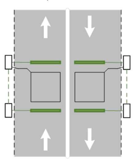
Figure 8.3.1 shows a typical Piezo-Loop-Piezo configuration used in WiM sites. For detailed configuration and placement of Piezo-Loop-Piezo at different road settings, showing all dimensions and associated road furniture, refer to SD1908 ITS – WIM Sensor Configuration Piezo-Loop-Piezo.
8.3.2Piezo-Piezo-Loop- Piezo-Piezo weigh-in-motion#
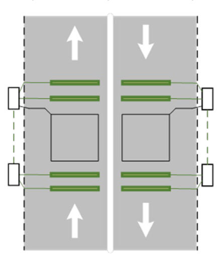
Figure 8.3.2 shows a typical Piezo-Piezo-Loop-Piezo-Piezo configuration used in WiM sites. This configuration is intended to reduce error by collecting more weighing samples of an axle. For detailed configuration and placement of Piezo-Piezo-Loop-Piezo-Piezo at different road settings, with all dimensions and associated road furniture, refer to SD1909 ITS – WIM Sensor Configuration Piezo-Piezo-Loop-Piezo-Piezo.
8.3.3Piezo-Piezo weigh-in-motion#
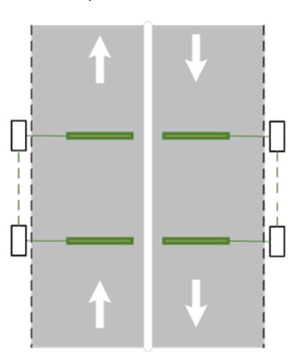
Figure 8.3.3 shows a typical Piezo-Piezo configuration used in WiM sites. This configuration does not have loop and is, therefore, unable to detect vehicle length. For detailed configuration and placement of Piezo-Piezo at different road settings and showing all dimensions and associated road furniture, refer to SD1910 ITS – WIM Sensor Configuration Piezo-Piezo.
8.3.4Strain gauge weigh-in-motion#
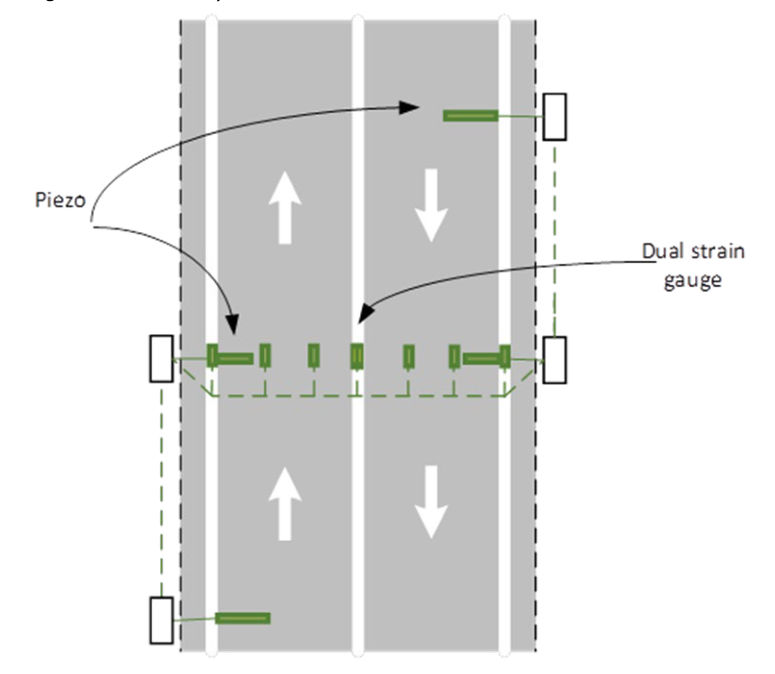
A typical strain gauge WiM site has 4 strain gauges installed on the soffit of the culvert under each lane to measure the deflection of the culvert caused by the weight load above it. Each lane shall also have a pair of piezoelectric sensors (1.83 m in length) installed on the pavement to detect vehicle speed. Figure 8.3.4 shows a typical strain gauge sensor configuration used in WiM sites. For detailed configuration and placement of strain gauge sensors at different road settings and with all dimensions and associated road furniture, refer to SD1911 ITS – WIM Sensor Configuration Strain Gauge Sensor.
The culvert of an ideal Strain Gauge WiM site shall exhibit the following characteristics:
- Reinforced concrete box culverts with simply supported lids of size 1200 mm span, with a depth of about 1200 mm is preferred. Inverted box culverts with spans of 1800 mm to 3000 mm are also acceptable. Short span inverted culverts under 1200 mm shall not be used.
- The depth of fill should be 600 mm at the minimum, assuming that roads have a 3% crossfall.
- The culvert should be square to the road.
- The soffit of the culvert should be free of cracks.
- The box culvert sections should be in modules 1200 mm long.
8.4Sensor Installation at high-speed weigh-in-motion site#
8.4.1Numbering of sensors#
8.4.1.1Loops#
The numbering of loops as described in Section 7.4.1.2 applies to numbering of loops in WiM sites.
8.4.1.2Piezoelectric sensors#
The numbering of loops as described in Section 7.4.1.3 applies to numbering piezoelectric sensors in WiM sites.
8.4.1.3Strain gauges#
Strain gauges in a WiM site shall be numbered sequentially, according to the numbering rules in Section 7.4.1.
8.4.2Inductive loop installation#
The inductive loop sensor installation details described in Section 7.4.3, and the relevant Standard Drawings listed in Section 8.2, apply to WiM sites.
8.4.3Piezoelectric sensor installation#
The piezoelectric sensor installation details described in Section 7.4.4 and the relevant Standard Drawings listed in Section 8.2 apply to WiM sites.
8.4.4Strain gauge installation#
In the department's weigh-in-motion application, strain gauges are transducers installed on the soffit of a culvert. The associated buffer amplifiers are installed in the field cabinet with the data acquisition system. Each transducer, its associated buffer amplifier and the cable that connects the transducer with the amplifier are pre matched and pre calibrated by the manufacturer and, therefore, are not interchangeable. The cables must not be cut, extended, or joined. Excessive cable length shall be coiled and stored inside field cabinet.
SD1911 ITS – WiM sensor configuration Strain Sensor shows the placement of strain gauges and associated devices within a culvert. Holes are drilled into the concrete structure that match the transducer mounting holes. Threaded expanding-head bolts are inserted, spacer washers are fitted, then the strain transducer is secured with dyna bolts.
When securing each strain transducer, care shall be exercised to prevent excessive deformation of the device which could cause permanent damage. Modest deformation will result in an electrical output offset that, in most cases, can be balanced by adjusting the associated buffer amplifier. Greater deformation may require the re tensioning of the securing bolts; however, in severe cases, the repositioning and reinstallation of the securing bolts may be necessary.
After the transducer is properly installed, a polystyrene foam thermal insulating cover is fitted over the transducer. The insulators of the cover can minimise temperature differential between the transducer and the culvert soffit where the transducer is mounted. Rapid ambient temperature changes around the transducer could occur due to wind gusts through the culvert.
Upon completion of installation, every strain measuring channel – that is, transducer in association with its buffer amplifier – shall be re-calibrated. Refer to manufacturer's instructions for calibration procedures.