7.3Sensor placement at traffic counter / vehicle classifier site#
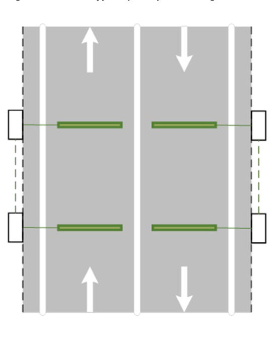
Traffic counter / vehicle classifier sites use a combination of sensing technologies, including inductive loop, piezoelectric device, and pneumatic tube.
Traffic counter / classifier sites are used for capturing traffic information such as volume counts and vehicle classification for traffic survey and planning purposes.
Traffic counter / vehicle classifier site can be:
- a)temporary installation, or
- b)permanent site.
7.3.1Temporary traffic counter / vehicle classifier sensors#
Temporary Sites support short term traffic survey and, therefore, the installation requires short turnaround time and, in many instances, also requires flexibility in terms of site selection. In temporary sites, loggers are installed when needed and recovered after the survey period concludes, whereas sensors can be either permanently set in the pavement or temporarily installed for the period of traffic survey.
Where permanent sensors are used in a temporary site, the sensors shall be as per the details in Section 7.3.2.
Where temporary sensors are used in a temporary site, these are typically pneumatic tubes which can be installed in different ways to suit number of lanes, direction of traffic flow and traffic volume. Two types of sites are considered, namely:
- single carriageway bi-directional sites, and
- single carriageway uni-directional sites.
All tube classifier installations shall be able to measure individual vehicles' travelling speed, to classify vehicles by Austroads 94 scheme defined in Austroads Guide to Traffic Management Part 3: Traffic Studies and Analysis Methods, and to report traffic volume by vehicle class and by speed. To do this, all tube installations shall consist of 2 pneumatic tube sensors perpendicular to the running lane and in parallel to each other exactly one or 2 metres apart, depending on the type of logger being used. Refer to SD1921 Intelligent Transport System – Axle-based vehicle classifier sensor configuration Tube-Tube for details.
The normal use of pneumatic tubes is to provide a roadside logger with the exact timing of axle events. These axle events are downloaded from the logger and converted to classification, direction and speed of each vehicle event, and traffic summary parameters: for example, volume by vehicle types.
The accuracy, in terms of vehicle classification and traffic parameters, of a site using pneumatic tubes is comparable with that of sites using twin piezoelectric sensors.
A tube classifier installation does not have capability to detect vehicle length.
7.3.1.1Single carriageway bi-directional sites#
When surveying a single carriageway site with bi-directional traffic, the sensor array configurations can be:
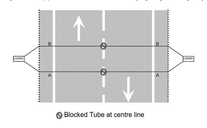
- Two tubes blocked at the centre of the road with one logger per lane (refer to Figure 7.3.1.1(a)), or
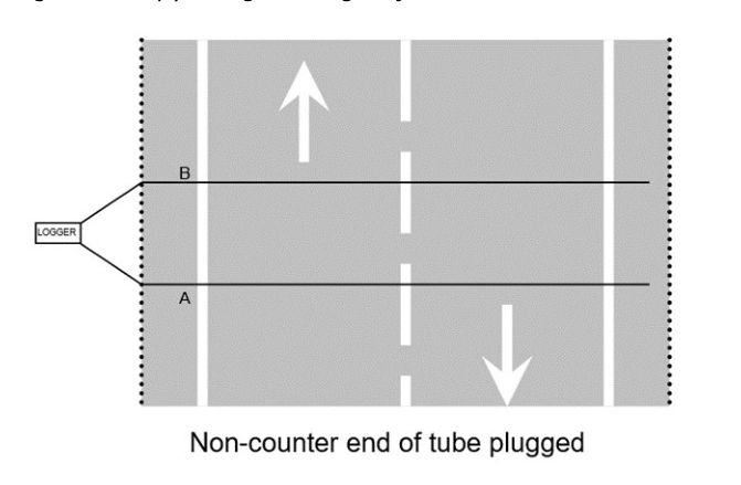
- Two tubes across both lanes with no block at the centre with a single logger for both lanes (refer to Figure 7.3.1.1(b)).
The first configuration (Figure 7.3.1.1(a)) will ensure the best possible accuracy of volume, classification, and speed data. Users must be aware that vehicles that are straddling lanes and that travel over both sensor arrays will be recorded in both lanes.
The second configuration Figure 7.3.1.1(b) is used on rural roads with less than 5000 AADT where it is feasible to use one single logger with one set of sensor array across both lanes. Consideration must be given to the level of degradation of data quality. A classification system based on one set of sensor array has finite probability of error when 2 vehicles in opposite directions traverse the sensors simultaneously, making it difficult to decipher the actual vehicle events. This configuration is only suitable for lower traffic volume situations.
7.3.1.2Single carriageway uni-directional sites#
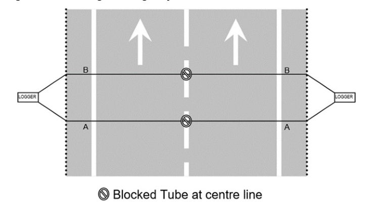
When surveying single carriageways with uni-directional traffic, the preferred sensor configuration is to use two tubes blocked at centre of the road with one logger per lane (refer to Figure 7.3.1.2). This arrangement will ensure the best possible accuracy of traffic volume, vehicle classification and speed data. Users must be aware that vehicles straddling lanes will be recorded in both lanes by the respective loggers. This will cause error if data of the loggers are treated separately as individual sites. This arrangement is only suitable for up to two lanes. Sites with more than 2 lanes shall use permanent sensor array.
7.3.2Permanent traffic counter / vehicle classifier sensors#
Permanent site is for long term data collection use. Both the logger and sensors are permanently installed at site. There are two vehicle classification categories for permanent classifier sensor configuration, namely:
- length-based vehicle classification, and
- axle-based vehicle classification.
Both classification categories depend on the measurement of speed. Permanent sites use a combination of sensing technologies: that is, inductive loop and piezoelectric device. Inductive loop enables the detection of vehicle body, whereas piezoelectric sensor allows the detection of vehicle axle. Vehicle travelling speed is calculated by measuring the time difference between 2 inductive loops or 2 piezoelectric sensors installed at a pre-determined spacing. Speed estimated using twin piezoelectric sensors is more accurate than that using twin loops.
7.3.2.1Length-based vehicle classification#
7.3.2.1.1Loop-Loop sensors#
Unless otherwise specified, sensor array used at a length-based traffic counter / vehicle classifier site, which can be installed on a single carriageway bi-directional or dual carriageway multilane road, will be of the Loop-Loop configuration type as shown in SD1920 ITS – Length based vehicle classifier sensor configuration Loop-Loop. Figure 7.3.2.1.1 depicts a typical sensor array configuration on a bi-directional carriageway.
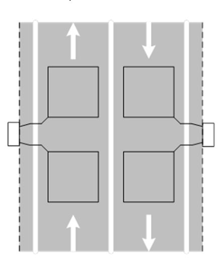
For detailed configuration and placement of Loop-Loop sensors, refer to SD1920 ITS – Length based vehicle classifier sensor configuration Loop-Loop.
7.3.2.2Axle-based vehicle classification#
For axle-based vehicle classification, the available options for sensors and their layout include:
- Piezo-Loop-Piezo sensors
- Loop-Piezo-Loop sensors, and
- Piezo-Piezo sensors
7.3.2.2.1Piezo-Loop-Piezo sensors#
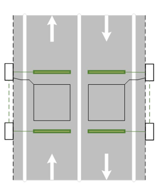
Figure 7.3.2.2.1 demonstrates a typical Piezo-Loop-Piezo configuration used in axle-based vehicle classification sites. Piezo-Loop-Piezo configuration achieves the highest accuracy level among all sensor configurations for permanent sites. Vehicle length parameter can also be detected with the use of inductive loop placed between the piezoelectric sensors. For detailed configuration and placement of piezo and loop sensors at different road settings, showing all dimensions and associated road furniture, refer to SD1918 ITS – Axle-based vehicle classifier sensor configuration Piezo-Loop-Piezo.
7.3.2.2.2Loop-Piezo-Loop sensors#
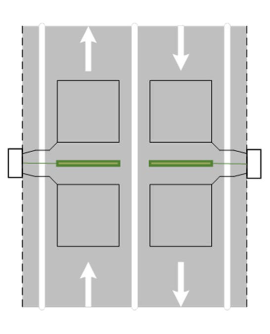
Figure 7.3.2.2.2 demonstrates a typical Loop-Piezo-Loop configuration used in sites for axle-based classification. Loop-Piezo-Loop configuration allows the reporting of vehicle axle configuration as well as length parameter. Since it uses 2 loops to estimate vehicle travelling speed, its accuracy is not as high as any site using 2 piezoelectric sensors. For detailed configuration and placement of piezo and loop sensors at different road settings, showing all dimensions and associated road furniture, refer to SD1917 ITS – Axle-based vehicle classifier sensor configuration Loop-Piezo-Loop.
7.3.2.2.3Piezo-Piezo sensors#
Figure 7.3.2.2.3 demonstrates a typical Piezo-Piezo configuration used in sites for axle-based classification. Piezo-Piezo configuration allows the reporting of vehicle axle configuration but without length parameter. Since it uses 2 piezoelectric sensors to estimate vehicle travelling speed, its accuracy is comparable to that of Piezo-Loop-Piezo configuration. For detailed configuration and placement of piezo sensors showing all dimensions and including the placement of associated road furniture, refer to SD1919 ITS – Axle-based vehicle classifier sensor configuration Piezo-Piezo.