7.4.2Pneumatic tube installation#
This section outlines a recommended 10-step procedure for the installation of air tube axle sensors based on field experience. It should be supplemented with the manufacturer(s) installation manual.
The recommended steps for the installation of air tube axle sensors are as follows:
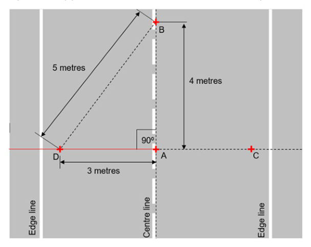
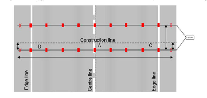
Step 1 – Construction Line: Use the 3-4-5 rule (Pythagoras' Theorem) to project a line (AD) perpendicular to the Centre line using the dimensions as shown in Figure 7.4.2(a). Extend the line DA towards C. This is the reference construction line from which tube locations can be offset.
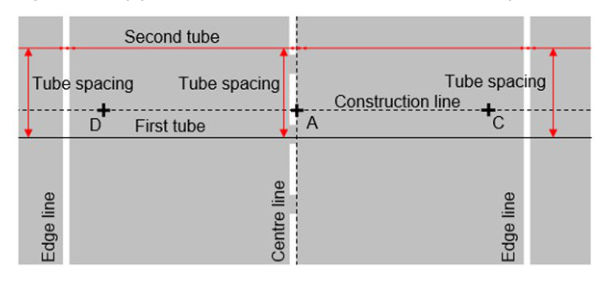
Step 2 – Determine location of tubes: Draw two lines parallel to the Construction Line. These are the locations of the first and second tubes respectively. Tube spacing shall be either 1 m ± 2 mm or 2 m ± 2 mm as determined by the Principal. Distance between the first tube and the Construction Line is 500 mm (refer to Figure 7.4.2(b)).
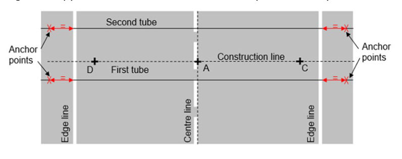
Step 3 – Anchor Points: Mark out anchor points by measuring equal distances into shoulder from edge lines. At sites with narrow seals and unsealed shoulders, the anchor points should be located 100 mm from edge of seal (refer to Figure 7.4.2(c)).
Step 4 – Tube placement: Prepare 2 round tubes of equal length. Tube length is determined by measuring from anchor point to anchor point, plus enough length to reach the logger at its securing points. If D tubes, instead of round tubes, are used across the traffic lanes, a round tube leader shall be joined to the D tubes by using a brass joiner and be sealed with tape. The round tube leaders for the first and second tubes shall be of equal length. If the tubes require being blocked at the centre line, this can be done by either tying a knot in the exact middle of the tubes or injecting a few squirts of silicone.
Step 5 –Tube anchoring and tensioning: Anchor tubes to road. The portion of a tube between the two anchor points shall be tensioned by stretching the tube by 10% longer during anchoring. It is critical to ensure that the un-tensioned portions of the two tubes, which leads to the classifier at site, are of same length.
Step 6 – Tube sealing: Where no logger is to be attached, seal the ends of each tube by tying 2 knots, or inserting a wood dowel and seal with tape.
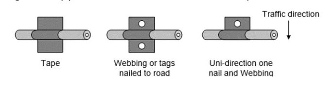
Step 7 – Tube initial securing: Secure tubes using any of the methods shown in Figure 7.4.2(d). to minimise lateral movement and maintain constant tube spacing.
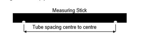
Step 8 – Tube spacing: Use a tape measure or measuring stick to ensure that both tubes are spaced correctly, as shown in Figure 7.4.2(e).
Step 9 – Tube final securing: Secure tubes on centre line, then on edge lines, and finally in the middle between centre line and edge lines as shown in Figure 7.4.2(f).
Step 10 – Connecting tubes to logger: Connect tubes into classifier. Ensure both tubes are connected to correct inputs.
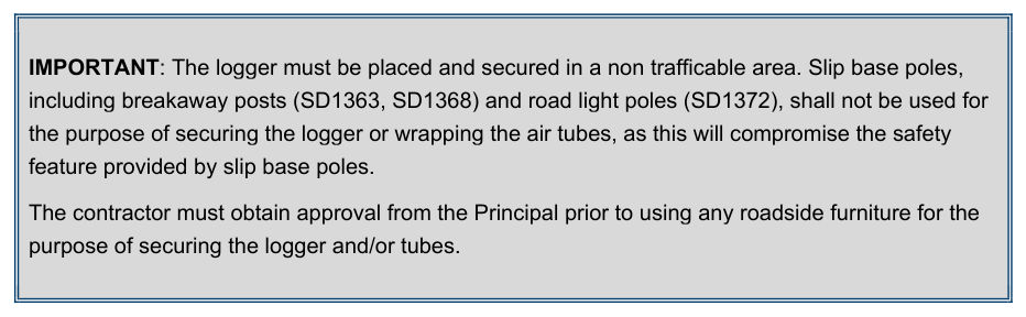
The contractor must obtain approval from the Principal prior to using any roadside furniture for the purpose of securing the logger and/or tubes.