9.4Sensor installation for active transport counter/classifier (ATCC) site#
9.4.1Numbering of sensors#
The numbering sequence of ATCC sensors shall be as detailed in Section 7.4.1.
9.4.2Pneumatic tube installation#
The installation of pneumatic tubes for ATCC shall be in accordance with Section 7.4.2.
9.4.3Piezoelectric sensor installation#
The installation of pneumatic tubes for ATCC shall be in accordance with Section 7.4.4.
9.4.4Passive infrared sensor installation#
A PIR sensor at a combined bicycle and pedestrian counting site detects traffic in both travelling directions and, therefore, requires only one PIR sensor at site.
A PIR sensor shall be fixed at 4.6 m above the centre line of the path to create a detection zone to cover traffic in both directions. Refer to Section 9.3.2.
For shared path, PIR sensor installation shall be in accordance with Section A of SD1929 ITS – Bicycle and pedestrian counter. The counting of pedestrian shall be adjusted to avoid error on double counting cyclists as pedestrians.
For separated path, the PIR sensor shall be mounted similarly to shared path but positioned directly above the footpath to detect pedestrian traffic only.
9.4.5Video analytics camera installation#
Unless specified by the manufacturer, a VA camera, should be mounted at height. This typically requires a mounting pole, enclosure, and cabling. Refer to SD1930 ITS – Video analytics active transport classifier. The VA camera must be properly aligned to meet the design objectives.
9.4.5.1Mounting pole#
The VA camera shall be mounted high enough to minimise vandalism but not too high to compromise system performance due to distorted object image or reduced object pixels in the image. Refer to Section 9.3.3.1.4. The mounting structure in its simplest form can be a pole. Should a site require a mounting height over 4.5 m, a swing pole should be considered for the convenience of maintenance.
The requirement and installation of any mounting structure shall comply with relevant departmental technical documents, including specifications, standard drawings, and guidelines.
9.4.5.2Enclosure#
VA cameras may require an enclosure to house supporting equipment, for example, edge processor, solar regulator, and battery. The enclosure shall comply with the requirements of MRTS226 Telecommunications Field Cabinets as a minimum.
9.4.5.3Cablings#
Cables must be concealed inside the mounting pole, conduits, or flexible conduits. Drip loops must be provided wherever applicable. Cabling entry points to the enclosure must be sealed and watertight.
9.4.5.4Installing and configuring VA camera#
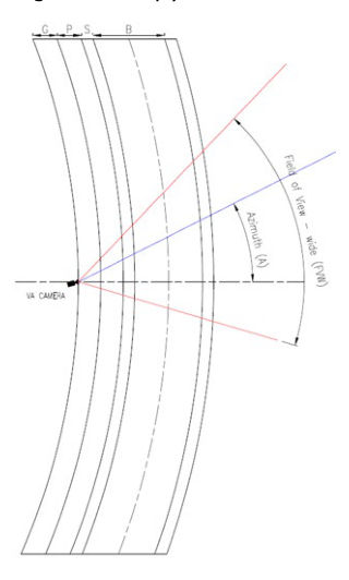
The installation and configuration of a VA camera must meet the specified mounting height, azimuth angle, depression angle in the design drawings, as well as thee coordinates of a control point which is a reference point on the floor to assist the installer to aim the camera. Refer to Section 9.3.3.1.