
2Design process#
2.2Risk assessment#
Replace: It is important to note that a Design Exceptions Report must be approved by the relevant Road Infrastructure Manager (RIM) and road authority if design exceptions are made or published standards or the AGTTM are not adhered to. with: Where variations to the treatments in the Queensland MUTCD Part 3 or QGTTM are proposed, a risk assessment certified in accordance with the requirements of Clause 1.9 of Queensland MUTCD Part 3 must be undertaken.
2.5Essential design principles#
2.5.3Signs#
Replace the entire Section 2.5.8 with the following: Signs indicate the nature of the hazard or work. For details on choosing an appropriate sign see AS1742.3. Once an appropriate sign is chosen, its location needs to be incorporated into the TGS. There are two steps in sign placement:
- 1.Locate the sign (see below).
- 2.Check sight distance (see Section 2.5.4).
Signs must be positioned a distance equal to that shown in Table 2.2 from the worksite or hazard (e.g. taper). Space successive signs (after the primary sign) the same distance as shown in Table 2.2 unless stated otherwise. If there is only a single advance warning sign on the approach, the sign must be positioned at double the spacing shown in Table 2.2 from the worksite or hazard.
| Speed (km/h) | Distance (m) |
|---|---|
| ≤55 | 15 |
| ≥56–65 | 45 |
| ≥66 | Equal to the speed (km/h) |
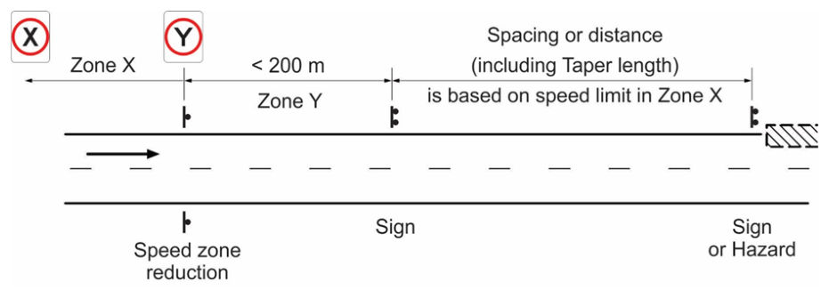
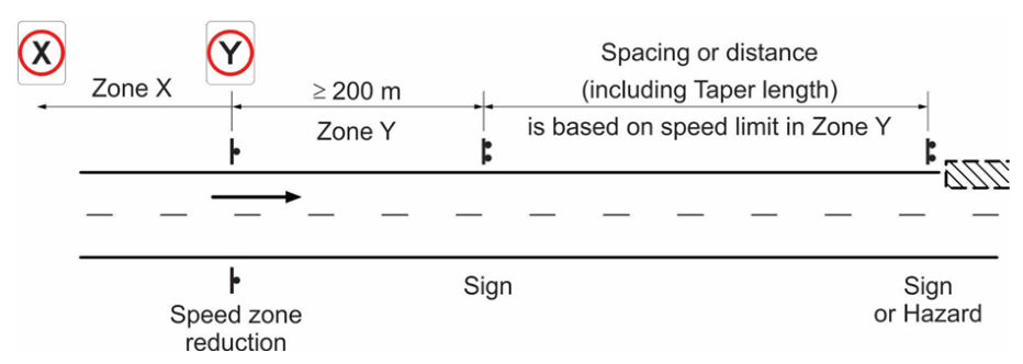
When designing spacing of advance warning signs, the speed to use in Table 2.2 must be as per Figure 2.2 rather than the intended travel speed. For example, if signs are positioned in the green zone, even when the speed changes from 110 km/h to 80 km/h, use the distance spacing which corresponds to a speed of 110 km/h in Table 2.2 for the first 200 m past the 80 km/h speed zone signs. If signs are positioned in the yellow zone, even when speed changes from 80 km/h to 60 km/h, use the distance which corresponds to a speed 80 km/h. Use 60 km/h for the blue zone and so on. In summary, always choose the higher speed limit in the first 200 m of the start of the new speed zone to ensure greater distance is provided to more accurately reflect potential travel speeds in these zones.
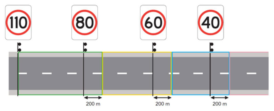
Where a sign spacing is partially within the 200 m zone after a speed limit change, use the higher speed limit in determining the relevant full spacing (even though only part of this spacing may be within this zone).
Tapers which are partially within the 200 m zone after a speed limit change are to use the higher speed limit in determining the relevant full taper length (even though only part of the taper length may be within this zone).
The following figures illustrate the relationship between a speed zone change and the spacing / distance applicable to signs or hazards (such as a taper).
Where traffic speed is substantially different (+/- 10 km/h or more) to the posted or temporary speed zone values, refer to Section 2.5.9 for the speed value to use in the tables.
Where site restrictions prevent the placing of required signs (e.g. local topography, median barriers, bridges) the following should be considered:
- moving signs away from the site restriction and installing additional signs
- using smaller signs, subject to the approval of the relevant authority, and
- using median barrier brackets to support signs, subject to the approval of the relevant authority.
Where a physical constraint on site impacts locating the sign(s) as per the spacing requirements in Table 2.2 and it is supported by a risk assessment, the TMD may increase this spacing requirement (up to a total maximum spacing of three times the spacing in Table 2.2) to suit the site conditions without requiring an RPEQ sign off.
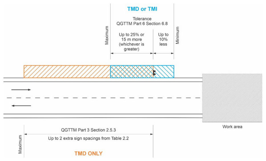
A TMD may apply tolerances (see AGTTM Part 6 Section 6.8) to the spacing requirements for signs and devices when preparing the design of a TGS.
See Figure 2.5.3(a) for the tolerances that apply to a sign spacing.
If a TMD applies a tolerance, which is either the minimum or maximum allowable (as per the above or AGTTM Part 6 Section 6.8), or is so close to the maximum or minimum such that a TMI also applying the maximum tolerance as per AGTTM Part 6 Section 6.8 on site may exceed the total allowable tolerance, or uses the provisions above to increase the spacing, the TMD must specify this distance as either a minimum or maximum (or provide the maximum or minimum value) on the TGS so that a tolerance is not also applied on site by the TMI which would then exceed any applicable limits.
While any sign may be installed in a permanent manner on posts sunk into the ground, signs required for works which will be in progress for longer than 14 days (that are not exclusively targeting pedestrians) should be installed in a permanent manner on posts sunk into the ground. Check that underground utilities are not located below and making holes is approved by the relevant road authority. Ensure regular site inspection, maintenance and securing practices occur in these circumstances. In these situations, the installation height of all temporary signs mounted in a permanent manner must be based on the requirements in AGTTM Part 6 Section 6.6.1 and AS1742.3 clause 4.3.2. Signs directed exclusively towards pedestrians must be installed at a height which will enable signs to be viewed easily by pedestrians (see QGTTM Part 6 Section 6.6.1).
The following must be considered when locating signs:
- Are signs appropriate for their location?
- Are signs located so that drivers' sight distance to the sign is maintained? Where they can be seen and read in adequate time by the intended road user? Sight distance for road users entering from side roads or private driveways must also be considered. The aim is to give road users sufficient warning when approaching a hazard (see Section 2.5.4)
- Are the signs placed at an appropriate height to ensure the drivers vision is maintained?
- Will signs be easily understood?
- Are repeater signs required?
- Have the risks associated with road users striking sign posts been considered?
- Do any additional measures need to be included to make the signage effective? E.g. For temporary speed limits, it is recommended that speed management treatments are included.
Sign placement should not make the sign itself, or its supports, a hazard to road workers, road users or local infrastructure (e.g. public transport). To reduce the risk of signs becoming hazards, the following treatments apply:
- Signs must be securely mounted. For road closures, consider mounting them on barricades or barriers to reduce risk of encroachment. Mounting on vehicles is also acceptable although caution and checks by an appropriately qualified person are recommended if this option is considered.
- Signs should be placed on the side of the road where work is being undertaken, though situations might arise where signs can only be put on the opposite side of the road.
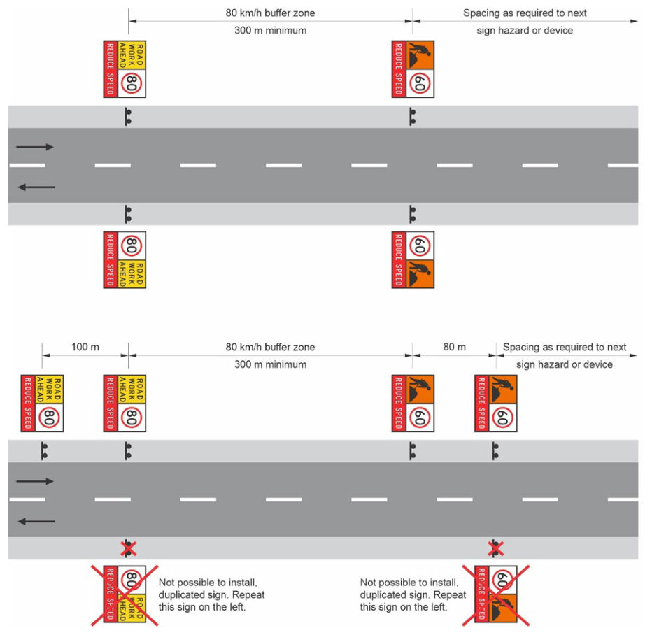
- To effectively communicate relevant messages to road users, signs should be placed on both sides of all multilane roads and should also be placed on both sides of high volume (7500 vpd or greater) roads. For temporary speed restriction signs, refer to Section 5.5.1 for requirements to install on both sides of the road. If sign duplication is not possible (for example, vegetation, barrier, inadequate width), the designer must document an alternative to ensure all road users are able to see signs. This may involve:
- 1placing signs on high temporary frames
- 2repeating signs on one side of the road
- 3closing one lane to be used for sign placement, and/or
- 4use of a variable message sign (VMS).
- Signs and sign support structures should be kept away from the edge of the roadway as outlined in AGTTM Part 6.
- Sign supports on the outside of curves and other vulnerable places should be avoided or the sign support should be protected. Signs used at roadwork sites should be frangible and not require protecting with additional devices such as road safety barriers.
- The Lane Status sign must be used where one or more lanes of a multiway roadway are closed to assist with providing advance warning. These signs must not to be used instead of signage of the closure. They should be used in conjunction with closure signage.
- Signs must not encroach on footpaths or bicycle lanes unless the path is wide enough to accommodate them. Consider vulnerable road users with impaired vision, mobility or cognitive limitations. A delineation device (e.g. a traffic cone) should be placed at the base of signs on footpaths or bicycle lanes. If the width of the footpath/cycle path is insufficient, then an appropriate TGS must be determined to manage the path users.
- Avoid placement that could direct road users into incorrect or dangerous situations.
- Signs or their supports must not obstruct visibility of other devices (e.g. signals, other signs, etc.), should not obstruct the view between different road users, or create a hazard for pedestrians or cyclists. Signs on narrow medians along the roadway might have reduced visibility. Increase the height of signs or consider using a VMS to improve visibility due to obstructions (e.g. parked cars).
- Signs must not be used where their legibility and effectiveness are compromised by contamination and/or marks and abrasions. Signs must be kept clean, especially in dusty or muddy conditions.
- Signs that conflict with the works must be removed or covered. Consider weather conditions (e.g. wind, rain) when choosing a suitable covering. It is essential that all signs at the worksite or varied travel route accurately represent the prevailing conditions at all times. Covering, altering or replacing signs may need to be approved by a RIM. Ensure that permanent signs are not damaged when doing so. Restore these signs when works are completed.
- Covering signs may be difficult due to height or size of the sign. When covering signs that are high, ensure this is done in a safe manner. All conflicting signs must be covered or removed, so it is important to identify any possible issues before implementation.
- Sign messages must not be permitted to be formed with tape, for example, Lane Status signs and mocking speed numerals in tape.
- Sign support structures must not be left in place without signs attached.
For merge tapers where the posted permanent speed limit of the road is 80 km/h or greater, the sign spacing between the lane status sign and the start of the merge taper may be increased to a distance of two sign spacings.
For merge tapers at any speed limit, where more than one lane is being closed, the sign spacing between the lane status sign and the start of the initial merge taper may be increased to a distance of two sign spacings.
A distance plate (TC2287) may be added to the lane status multi message sign to indicate the distance from the lane status sign to the start of the merge taper.
If sign duplication is not possible and the designer has chosen to repeat signs on the one side of the road, repeated signs are located a minimum of one sign spacing from the original sign.
If there are spacing requirements between the original sign being repeated and another sign, device, or hazard beyond the sign (in the direction of travel), then this spacing requirement will now apply to the repeated sign. Any spacing requirements between the original sign being repeated and another sign, device, or hazard prior to the sign (in the direction of travel), will remain as a requirement to the original sign being repeated.
See Figure 2.5.3(b) for an example showing signs for one direction of travel only on a two-way road. This figure does not include all traffic control devices required and is not to be used as a TGS diagram.
2.5.4Sight distance#
Add the following note to Table 2.3:
2.5.7Traffic lanes#
Replace Table 2.4 with the following:
| Mid-block (one direction) (vph) | Within 200 m of controlled intersection (one direction) (vph)^ | Desirable number of open lanes for direction considered |
|---|---|---|
| ≤ 1000 | ≤ 500* | 1 |
| 1001–2000 | 501–1000 | 2 |
| 2001–3000 | 1001–1500 | 3 |
| 3001–4000 | 1501–2000 | 4 |
* Right turns out of the single lane may need to be prohibited, depending on the proportion of heavy vehicles and the volume of opposing traffic. ^ This is a controlled intersection where traffic in the directions being considered is controlled (by traffic signals, roundabout, GIVE WAY or STOP signs).
- Pavement surface is rough or unsealed – reduce traffic volume by 30%.
- Horizontal geometry through the restriction is reduced to a speed value of less than 40 km/h – reduce volume by 50%.
- Volume of heavy vehicles exceeds 10 % and downward, level or easy upgrade – reduce traffic volume by 20%.
- Volume of heavy vehicles exceeds 10 % and sustained upgrades > 5% – reduce traffic volume by 40%.
2.5.8Lane widths#
Replace the entire Section 2.5.8 with the following:
Lanes carrying traffic around, through or past a roadworks site must be as per Table 2.5. Lane widths should consider accommodating the swept path of large vehicles expected to negotiate the roadworks site.
| Criteria | Lane width (m) |
|---|---|
| General lane widths | |
| ≤60 km/h | Minimum 3.0* |
| 70, 80 or 90 km/h | Minimum 3.2* |
| ≥100 km/h | Minimum 3.4* |
| Curve with radius 100–250 m | Add curve widening of 0.5 m per lane |
| Curve with radius <100 m | In addition to the curve widening of 0.5 m per lane, consider the swept path of long vehicles (for example, buses, trams) |
| Two-way residential street | Minimum of 5.5 (sum both ways) |
| Shuttle flow operation | |
| Shuttle flow with active control (by traffic controllers or PTCDs) | Minimum 3.0* |
| Shuttle flow, without active control on residential streets, includes no control or the use of GIVE WAY and ONE WAY signs (see Section 5.4.4). | Minimum 3.0* and Maximum 3.5 to ensure vehicles take turns using a single lane |
Table in words
- For general lane widths at ≤60 km/h, the lane width is Minimum 3.0*.
- For general lane widths at 70, 80 or 90 km/h, the lane width is Minimum 3.2*.
- For general lane widths at ≥100 km/h, the lane width is Minimum 3.4*.
- For a curve with radius 100–250 m, add curve widening of 0.5 m per lane.
- For a curve with radius <100 m, in addition to the curve widening of 0.5 m per lane, consider the swept path of long vehicles (for example, buses, trams).
- For a two-way residential street, the lane width is Minimum of 5.5 (sum both ways).
- For shuttle flow with active control (by traffic controllers or PTCDs), the lane width is Minimum 3.0*.
- For shuttle flow, without active control on residential streets, includes no control or the use of GIVE WAY and ONE WAY signs (see Section 5.4.4), the lane width is Minimum 3.0* and Maximum 3.5 to ensure vehicles take turns using a single lane.
*Temporary minimum lane widths are not to be greater than existing lane widths. This minimum temporary lane width does not apply to curves of radius 250 m or less, or locations where there are fixed vertical obstructions such as fences or safety barriers within 30 cm of the edge of the lane on one or both sides. Where these conditions apply, consider widths wider than those listed previously to accommodate large vehicles. The speed to be used when considering lane width requirements is the speed limit (permanent or reduced) which is applicable to that length of road.
Consideration must also be given to cyclists and pedestrians (see Sections 3.10, 4.10 and 5.13 for further details on traffic management regarding pedestrians and cyclists).
When selecting lane widths, especially when travel paths are confined on each side by physical barriers and / or hazards (e.g. excavations or safety barriers) for a significant distance, it is important to consider any impact of breakdowns and congestion for emergency vehicle access and on traffic flow. Refer to QGTTM Part 2 Section 3.3.4 for more detail.
Where there is a change in speed limit, the minimum lane width requirements may also change with lane widths based on the applicable speed limit at that location. Changes to lane widths will apply at the change in speed limit, with the transition to the new lane width commencing at the speed limit change location. The transition to the new lane width must occur at a rate which matches the transition rate for a lateral shift (see Table 5.7) of the same distance (the lane width change) in the same location (note the 200 m value for Figure 2.2 applies to taper lengths): for example, for a lane width reduction of 0.4 m, as the lateral shift values are based on a full 3.5 m shift, the equivalent recommended lateral shift distance would be divided by approximately 8.7 (3.5 / 0.4) to establish the taper length required for the 0.4 m transition in lane widths.
As an example, a transition distance for a new speed limit (60 km/h) and lane width (3.0 m), from a 100 km/h zone with an existing 3.5 m lane width, will commence at the 60 km/h sign and transition the 0.5 m change in width over a distance of approximately 15 m, based on a 3.5 m lateral shift at 100 km/h being 100 m long (100 / (3.5 / 0.5) = 14.3).
2.6Variations to design#
Refer to Clause 1.9 of the Queensland MUTCD Part 3.
2.7Combining different works protection methods#
Combining different works protection methods at the one site is permitted where the requirements for the different works protection methods are met.
Within a static work site, a mobile works treatment (QGTTM Part 4) or short-term low-impact works protection methods (QGTTM Part 5) may be used when appropriate and when satisfying the risk assessment and other provisions and criteria of the different works protection methods.
As per requirements in QGTTM Part 5 Section 3.6, a static work site must not be created solely for enabling a speed reduction which would permit short-term low-impact work protection methods which require a lower speed limit then applies to be used.
When a mobile works treatment (QGTTM Part 4) or short-term low-impact works protection methods (QGTTM Part 5) are used in a static work site, the respective requirements of QGTTM Part 4 or Part 5 must be applied.