5.9Transition area#
5.9.1Tapers#
In subsection 'Traffic control taper', add the following:
For shuttle flow operations, the traffic control taper must start a minimum of 6 m from the traffic controller or PTCD.
Replace the title for Table 5.8:
Table 5.8: Distance between tapers
with
Table 5.8: Minimum distance between tapers
Replace the text following Table 5.8:
The speed to use in Table 2.2 and 5.8 must be as per Figure 2.2 of Section 2.5.3. For details on how to use delineation devices see Section 5.4.
with
The speed value used in Tables 5.7 and 5.8 shall be as per Figure 2.2 of Section 2.5.3 – the 200 m zone in Figure 2.2 applies to the recommended length and recommended spacing of tapers. For the spacing of delineation devices at tapers, see Section 5.4. The 200 m zone in Figure 2.2 does not apply to delineation spacing. Where the posted permanent speed limit of the road is 80 km/h or greater, the recommended taper length for merge tapers (Table 5.7) and the recommended distance between merge tapers (Table 5.8) may be increased and be based on the posted permanent speed limit of the road.
In subsection 'Merge taper', add the following:
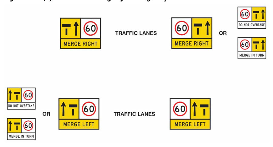
When signing merge tapers, the multi-message signs on each side of the multilane road on approach to the merge taper may be different. The MERGE LEFT / MERGE RIGHT panel should be included with the lane status panel for the lane which is required to merge (must change lanes); however, for the lane where no action is required as this lane continues, the MERGE LEFT / MERGE RIGHT panel may be replaced with either a DO NOT OVERTAKE or MERGE IN TURN panel as shown in the following Figure 5.9.1(a).
In subsection 'Multiple tapers', add the following:
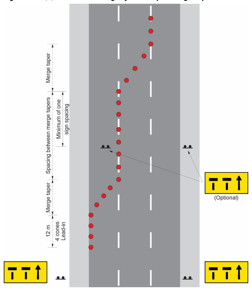
When signing multiple merge tapers, the following lane status sign configuration and location requirements will apply:
- All lane status signs must display the final lane configuration regardless of their location.
- A lane status sign must be located a minimum of a single sign spacing prior to the start of the first merge taper; however, as more than one lane is merging, this spacing may be increased to a distance of two sign spacings (see Section 2.5.3).
- A repeater lane status sign may be installed in the area between the two merge tapers and, if used, should be located a minimum of a single sign spacing prior to the start of the second merge taper.
The following Figure 5.9.1(b) is an example of the lane status sign configuration and location for a road with multiple merge tapers. This Figure does not include all traffic control devices required and is not to be used as a TGS diagram.
In subsection 'Designing a taper', replace the fifth and sixth dot points:
- Tapers must not start or end within 50 m of an intersection on Category 2 roads. In this case, the start of the taper is the point where the shift / merge finishes, and the end of the taper is where closed lanes are re-opened.
- Tapers must not start or end within 100 m of an intersection or on / off-ramp on Category 3 roads. In this case, the start of the taper is the point where the shift / merge finishes, and the end of the taper is where closed lanes are re-opened.
with:
- Merge tapers must not start or end:
- within 50 m of an intersection (both approach and departure sides) on a controlled leg of an intersection on a Category 2 road
- within 100 m of an intersection (both approach and departure side) located on a ramp from / to a Category 3 road, or
- within 100 m of a ramp (on or off) on a Category 3 road.
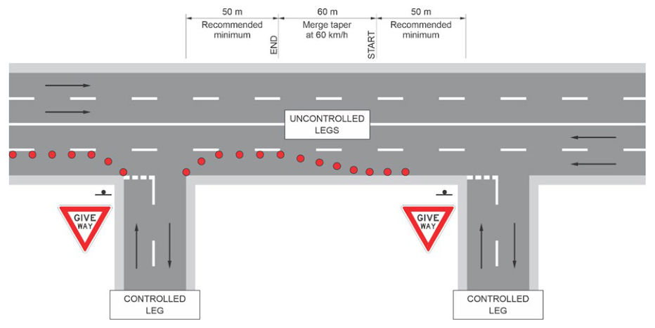
- Merge tapers located on an uncontrolled leg of an intersection on a Category 2 road should not start or end within 50 m of the intersection (both approach and departure sides).
- Merge tapers must not be implemented through / across an intersection or ramp.
- Lateral shift tapers (excluding at contraflow transition points) must not be implemented through / across an intersection or ramp.
- Where provided at contraflow transition points, the management of the other approaches to the intersection will be critical.
In subsection 'Designing a taper', add the following:
When considering the space requirements for a merge taper, the terminology referring to a controlled leg or uncontrolled leg of an intersection on a Category 2 road is different to a controlled intersection. Controlled legs are those approaches to an intersection controlled by traffic signals, roundabout give way signs, give way signs, or stop signs. In some cases, a controlled intersection may have uncontrolled legs, which are not subject to any formal control method.
Figure 5.9.1(c) shows an example of a merge taper on a Category 2 road with a 60 km/h speed limit that includes intersections with minor side streets (GIVE WAY or STOP signs on the side streets only). The side street legs are controlled while the multilane road has uncontrolled legs through these controlled intersections.
5.9.2Chicanes#
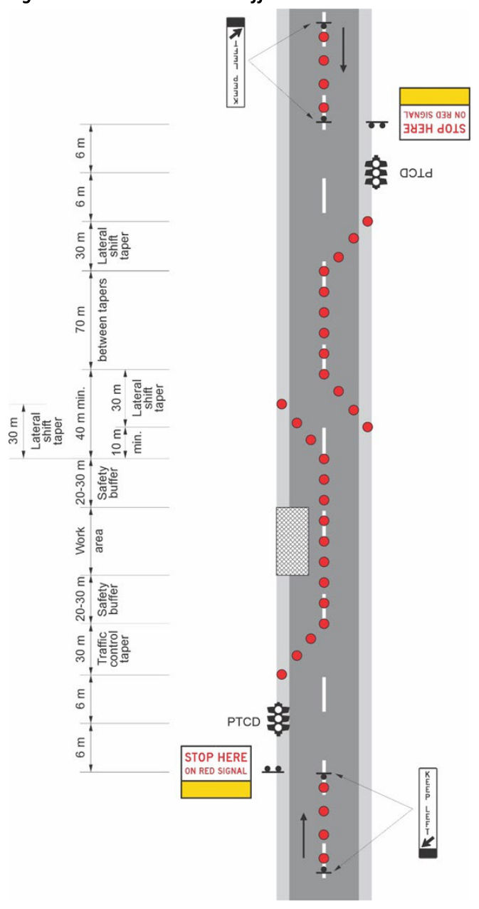
A chicane is also a useful treatment when using shuttle flow traffic control to ensure vehicles return to the correct side of the road and should be implemented when the site is unattended.
Figure 5.9.2 illustrates an example of a chicane used with shuttle flow and signal traffic control on a road with a 60 km/h speed limit. This diagram does not include all traffic control devices required and is not to be used as a TGS diagram.
5.9.4Closing the shoulder#
Shoulders are not generally used as traffic lanes; however, shoulders may be used by cyclists and, in some cases, by motorcyclists. Parking lanes may also appear to some road users as possible traffic lanes.
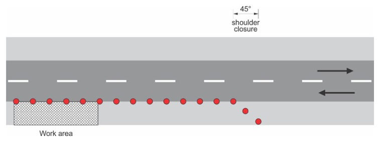
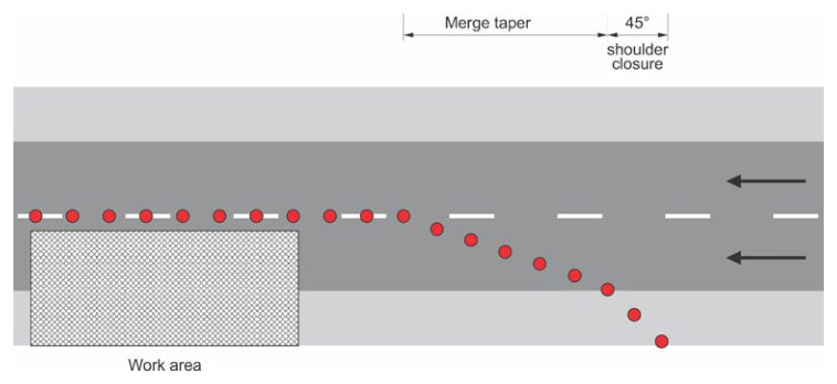
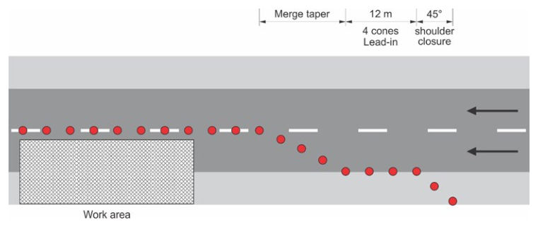
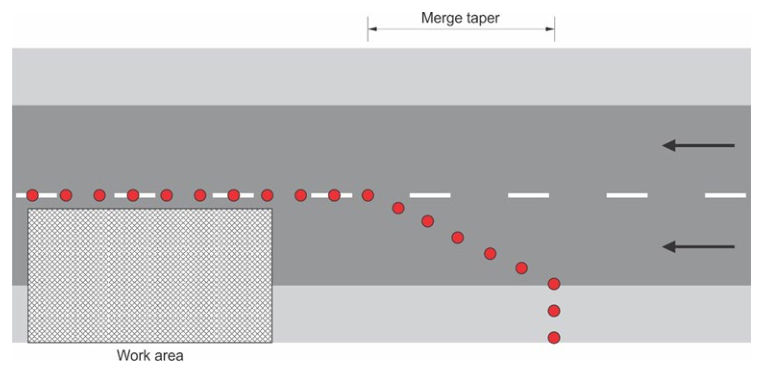
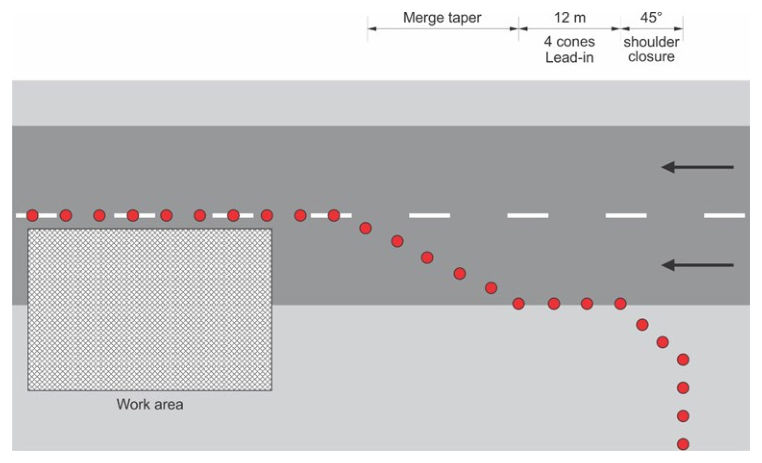
Where works require the closure of the area outside of the traffic lane (shoulder), to ensure road users do not inadvertently traverse the area behind the delineation of works, the following options apply:
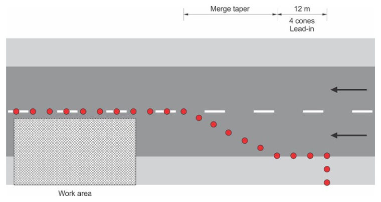
- 1.Where the shoulder may be used by cyclists and, in some cases, motorcyclists, a short taper at a 45 degree angle to traffic should be provided (see Figures 5.9.4(a), 5.9.4(b) and 5.9.4(c)). This is the preferred method of closing a shoulder.
- 2.Where the shoulder is unlikely to be used by other road users, subject to a risk assessment, a square closure may be implemented (see Figures 5.9.4(d) and 5.9.4(e)).
- 3.Where there is a very wide shoulder (for example, wide road reserves in rural towns or where angle parking is provided), subject to a risk assessment, a combination of these options may be implemented (see Figure 5.9.4(f)).
Devices which may be used to close the shoulder include traffic cones, bollards, Temporary Hazard markers, barrier boards, or a combination of these, depending on the site characteristics. The following Figures do not include all traffic control devices required and are not to be used as TGS diagrams.