4.8Advance warning area#
Replace the entire Section 4.8 with the following:
The advance warning area is critical to the success of ‘through’ traffic management and aims to provide:
- no surprises to road users regarding traffic control
- a controlled release of relevant information (e.g. signs)
- repeated information where pertinent to emphasise danger.
It can also reduce traffic in the area by inducing road users to actively plan alternative routes where possible (refer to AGTTM Part 2). Advance warning signs and information also strengthen the delineation of a route and ensure that road users can safely and effectively navigate their way to their intended destinations. Note the following steps in conjunction with Figure 4.4, Figure 4.5 and Figure 4.6 examples when designing the advance warning area for ‘through’ methods:
- 1.Identify the PTCD or traffic controller position.
- 2.STOP HERE ON RED SIGNAL and STOP HERE WHEN DIRECTED must be installed where warranted in accordance with Queensland MUTCD Part 3. When used, they must be installed 6 m before the PTCD / traffic control position in the direction of travel. A temporary STOP line may be installed using temporary removable road marking tape.
- 3.Four cones should be placed on the centreline spaced 4 m apart starting from the STOP HERE ON RED SIGNAL or STOP HERE WHEN DIRECTED sign position (downstream). A Temporary Hazard marker (T5-7) or KEEP LEFT sign (R2-3-Q01) may be installed at the start of the row of four cones (on both ends of the four cones) to direct traffic to the correct travel path if needed.
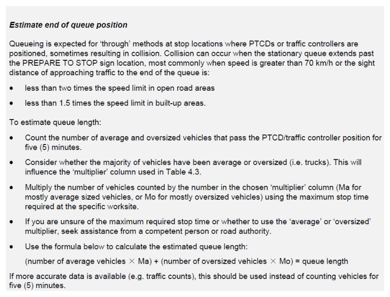
- 4.Estimate end-of-queue position (via the box instructions in Austroads Guide to Temporary Traffic Management Part 3 Section 4.8). A marker (for example, a cone or bollard) should be placed on the shoulder at the predicted end-of-queue to assist the traffic controller and traffic management implementer to monitor queue lengths.
- 5.A PREPARE TO STOP sign must be placed in conjunction with the Boom Barrier or Traffic Controller (symbolic) or Signals Ahead sign a minimum distance as shown in Table 2.3 from the predicted end-of-queue, not the PTCD / traffic controller position. This is the primary PREPARE TO STOP sign.
If the PREPARE TO STOP sign is more than 240 m from the traffic controller, an additional PREPARE TO STOP sign must be placed 120 m from the traffic controller (see Figure 4.4 and Figure 4.5). The primary purpose of this sign is to protect the traffic controller. This is the additional PREPARE TO STOP sign.
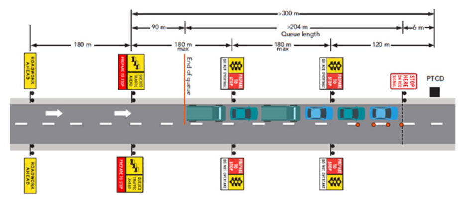
If visibility is lost or the distance from the PREPARE TO STOP sign to the PTCD / traffic controller is more than 300 m, the use of repeater PREPARE TO STOP signs should be considered as per Table 4.4(a).
Where these conditions are met and the additional or repeater PREPARE TO STOP signage is required, a Queued Traffic Ahead multi-message sign assembly may be used as the primary PREPARE TO STOP sign. If used, this multi-message sign assembly must include the Queued Traffic (symbolic) (TM1 47A), QUEUED TRAFFIC AHEAD (TM1 46A) and the PREPARE TO STOP (TM1-18B), see Figure 4.8(a) following.
The primary PREPARE TO STOP must be installed in advance of the predicted end-of-queue in accordance with Austroads Guide to Temporary Traffic Management Part 3 Table 2.3.
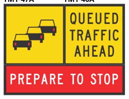
TM1-47A · TM1-46A · TM1-18B
Where this assembly is used, the preferred method of display is to locate the QUEUED TRAFFIC AHEAD text panel (TM1-46A) closest to traffic.
- 6.A ROADWORK AHEAD sign, or VMS must be placed as per Table 4.4(b) in advance of the primary PREPARE TO STOP sign position discussed in Step 5, except for advance signs on side roads, where the requirement of Step 9 will apply.
- 7.Surges in traffic demand can occur so adequate monitoring of the queue must be undertaken to minimise the risk of end-of-queue collision. If the end of queue extends beyond the estimated end-of-queue position, adequate warning of the end of queue must be provided. The options available include:
- a)initially, when traffic queues are approaching the estimated end-of-queue position, the traffic controllers should advise the site supervisor that traffic queues are approaching their maximum length and contingency planning may need to be implemented
- b)as an interim measure, the traffic controllers may adjust their timing or give priority to one approach to minimise queuing from the key direction
- c) if adjusting timings is not successful in managing queue lengths, implement a pre-designed contingency plan to cater for the longer queue lengths being experienced – this will need to be completed by the traffic management implementer while traffic controllers continue to control traffic, and
- d) if a pre-designed contingency plan is not provided, seek urgent advice from the traffic management designer for the works.
- 8.Where the speed limit on approach to the traffic control station is greater than 60km/h, a 60 km/h speed zone must be commenced at least one sign spacing (Table 2.2) in advance of the primary PREPARE TO STOP sign. This does not apply to situations where the traffic control station is located down a side road and the speed of traffic on approach to the traffic control station and the end of the traffic queue is less than 60 km/h through other controls (such as the traffic needing to turn onto the side road at a lower speed). Speed signs may be required on the side road if the speed of traffic on the side road may exceed 60km/h prior to the traffic control station or the end of the traffic queue. See Section 4.8.1 for more information on speed limits for traffic control stations on a through road near a side road.
- 9.Where intersections are located within the advance warning area (between the traffic control station and the ROADWORK AHEAD or VMS sign), see Section 4.8.1 for the signing requirements for traffic on or entering from side roads.
- 10.Provide additional devices and methods for avoiding end-of-queue collisions as required in Section 4.8.3.
- 11.For shuttle flow operations, the traffic control taper must start a minimum of 6 m from the traffic control station.
Duplicate the speed limit signs on both sides of the road and install repeater speed limit signs as required in Section 5.5.1.
As per AGTTM Part 7 Section 2.6.3, when used in a multi-message situation, the PREPARE TO STOP panel must be placed closest to the travel way and that the 600 x 600 version of this sign is used as illustrated in Figure 4.8(b), excluding where the use of the 1200 x 300 version is specifically permitted by QGTTM.

For the purpose of estimating the end-of-queue position only, the term 'oversized vehicles' also includes 'heavy vehicles'.
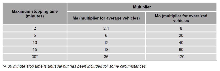
When estimating the queue length, Table 4.3 uses an average vehicle length of 6 m and an average heavy vehicle length of 20 m for a five minute stopping time (based on the five minute traffic count) and then adjusts the multipliers for other stopping time values.
Where very long vehicles are expected (for example outback and mining routes or routes where most vehicles are towing), then to ensure estimated queue lengths are as accurate as possible, an average length per vehicle that matches the actual traffic mix expected at that location should be used.
The estimated queue length must be at least a minimum of one average vehicle plus one heavy vehicle (of a length which may be applicable to the site). Part lengths of vehicles must be rounded up when estimating queue lengths.
To calculate the 'maximum stopping time' value used in Table 4.3 for each approach, the Traffic Management Designer must estimate the likely duration of time that queued traffic will be stopped at a traffic control station. Calculating the maximum stopping time needs to include the total time from when the traffic controller stops traffic, through until the same traffic controller releases traffic for the next cycle from that approach. This would typically include the following considerations:
- the time taken for the traffic queue from one approach to pass the traffic control station and travel the length of the closure
- the time for the queue at the other end of the site to leave that traffic control station and also travel the length of the closure (this may commence at the same time as the other queue or following the completion of the other queues travel if shuttle flow is in operation)
- if traffic queues are held for a period (with no traffic traveling through or past the site), then this hold time will also need to be included
- a factor of safety may also be allowed for vehicles travelling the closure below the signed speed limit, and
- if more than two traffic control stations (one each end) are in operation, depending on the operating characteristics of the roadworks site, the time for each queue to be released and travel through the roadworks site may need to be considered and included.
The 'maximum stopping time' value will be used in Table 4.3 to determine the multipliers to be used with the number and type of vehicle (average or heavy) from the five minute count or calculation.
| Speed (km/h)* | Distance (m) |
|---|---|
| ≤55 | 60 |
| ≥56 | 180 |
* The 'Speed' value to be used for the maximum spacing for repeater PREPARE TO STOP signs is the actual posted speed (temporary or permanent) which applies (this will generally be 60 km/h but may be less) where the repeater spacing is required. If the speed limit changes within a repeater spacing, use the spacing for the lower speed limit.
| Speed (km/h)^ | Distance (m) |
|---|---|
| ≤55 | 30 |
| ≥56–65 | 90 |
| ≥66–75 | 140 |
| ≥76–85 | 240 |
| ≥86 | Four times the speed (km/h) |
^The 'Speed' value to be used for the minimum distance from the ROADWORK AHEAD or variable message sign to the primary PREPARE TO STOP sign is the actual permanent posted speed of the road prior to any reduction for the roadworks.
An estimated end-of-queue position is to be determined for the approach to each traffic control station and is to be based on the maximum expected traffic flow on that approach during the time traffic control will be in operation.
The count or estimate of the number of average and heavy vehicles during a five-minute period at a site may be completed using the following in order of preference:
- 1.Actual five-minute count of vehicles during the peak time the site will be occupied. This five-minute count is based on the vehicles approaching the selected traffic control station from the approach to be controlled by that station (not a sum of both directions of traffic). Consideration of peak traffic flow direction may be needed.
- 2.If a five-minute count is not possible, use annual average daily traffic (AADT) values with hourly breakdowns and percentage heavy vehicle data. To estimate the five-minute count, select the peak hourly period during the time the site will be occupied and divide by 12 to get an estimated five-minute value. Divide this by two if the AADT is for a two-way road. Use the percentage heavy vehicles information with this value to estimate the number of heavy vehicles for this five-minute period.
- 3.If a five-minute count is not possible, and AADT values with hourly breakdowns are not available, use AADT values and percentage heavy vehicle data. To estimate the five-minute count, firstly divide the AADT by a factor of 10 (to get an estimated hourly count) and then divide this by 12 to get an estimated five-minute value. Divide this by two if the AADT is for a two-way road. Use the percentage heavy vehicles information with this value to estimate the number of heavy vehicles for this five-minute period.
AADT information for state-controlled roads can be located on the Queensland Open Data Portal – Traffic Census data.
The duplication of the advance warning signs for a traffic control station as indicated in Figures 4.4, 4.5 and 4.6 below is not a specific requirement. Signs are to be duplicated in accordance with the requirements in Section 2.5.3 and Section 5.5.1 for speed signs.
Figure 4.4 illustrates an example of sign positioning for queues as per the steps above for a speed of 60 km/h where the PREPARE TO STOP sign is less than or equal to 240 m away from the PTCD/traffic controller. This diagram is not an example of how to install all traffic control devices and is not to be used as a TGS diagram.
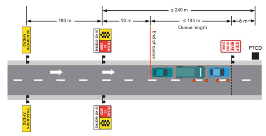
Figure 4.5 illustrates an example of sign positioning for queues as per steps above for a speed of 60 km/h where the primary PREPARE TO STOP sign is more than 240 m, but less than or equal to 300 m away from the PTCD/traffic controller. This diagram is not an example of how to install all traffic control devices and is not to be used as a TGS diagram.
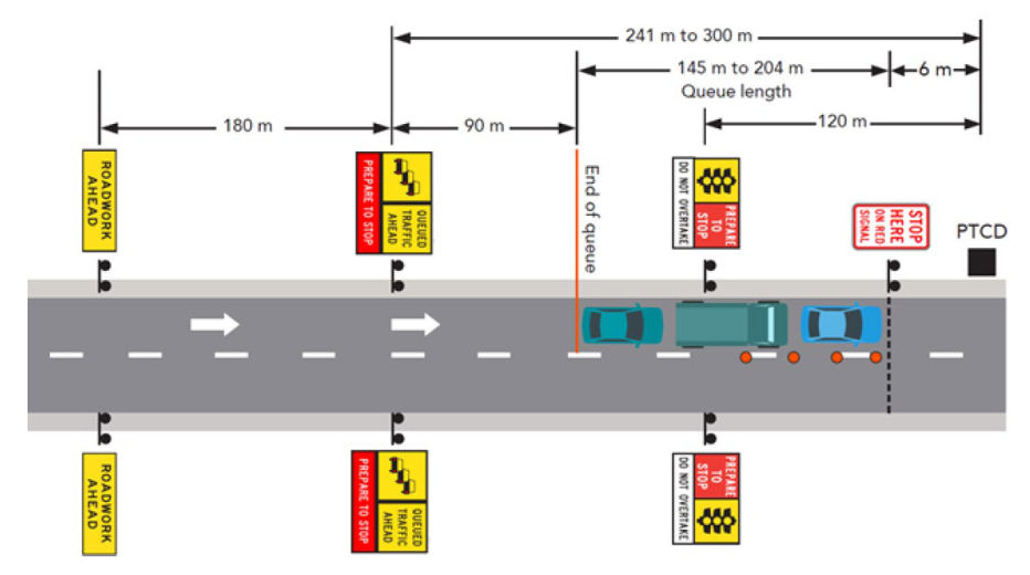
Figure 4.6 illustrates an example of sign positioning for queues as per steps above for a speed of 60 km/h where the primary PREPARE TO STOP sign is more 300 m away from the PTCD/traffic controller. This diagram is not an example of how to install all traffic control devices and is not to be used as a TGS diagram.
While using two lanes for queuing is possible and may reduce the physical length of the queue, it does come with additional risks related to driver behaviour and capability. Lane utilisation may not be evenly distributed, as drivers often favour one lane over another, especially when approaching a merge point. Many drivers tend to merge earlier than necessary, which can cause the end of the queue to extend further back, and lead to increased end of queue risk. Driver aggression and frustration may also be experienced by those in the queue due to motorists cutting in late, which may not be the best frame of mind for drivers to be in when approaching the traffic control station or passing the workers on the site.
On multi-lane approaches, drivers are generally less prepared to stop, as they are not expecting this, which can create safety issues. The preference is to utilise queuing in a single lane where possible to minimise these risks.
If using two lanes for queuing, it's crucial to carefully assess the specific site conditions, implement additional safety measures, and closely monitor the actual queue formation during operation to ensure adequate warning of the traffic queue ahead is provided.
When multiple lanes are available within the expected queue distance, the queue length in any full width traffic lane may be used for queueing (the length of the merge taper for the merging lane must not be included in the queue length calculation). Additional queue length may be added to mitigate the risks of drivers favouring one lane over the other for queueing.
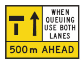
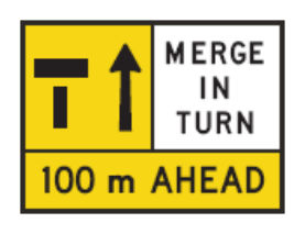
When using two lanes for queueing, consider the use of the WHEN QUEUEING USE BOTH LANES panel (TM2-Q04) and/or the MERGE IN TURN [panel (TM2-Q05) with the lane status signs.