6.11Clear Zone#
This section on clear zones will apply when clear zones are identified as being required elsewhere in the TTM technical documents. Typically, clear zones will apply to stored plant or materials (see Section 7.4.1), and when traffic is laterally shifted onto a different alignment (see Section 6.5).
The identification of hazards is generally based on the use of the clear zone concept to define the area beside the road that is of most interest in terms of roadside safety.
A clear zone is the area adjacent to the traffic lane that should be kept free from features that would be potentially hazardous to errant vehicles. The clear zone is a compromise between the recovery area for every errant vehicle (allowing a driver to stop safely or safely regain control of a vehicle that has left the road), the cost of providing that area and the probability of an errant vehicle encountering a hazard. The clear zone should be kept free of non-frangible hazards where economically and environmentally possible. Alternatively, hazards within the clear zone should be treated to make them safe or be shielded by a safety barrier.
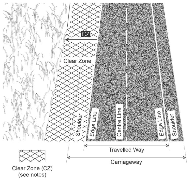
The clear zone commences from the closest edge of the through travelled way for the direction of travel and is the total roadside border area available for safe use by errant vehicles. This clear zone area may consist of a shoulder, a verge, and a recoverable slope.
While the clear zone concept draws on a wide range of experience and research, engineering judgement should also be applied in the determination of lateral position requirements. The guidance here should be regarded as a supplement to aid in exercising this judgement and not as a substitute for it.
Roadside hazards should be located outside the clear zone or be protected by a suitable and approved safety barrier. If a safety barrier is installed no portion of the hazard is to be located within the deflection limits of the safety barrier.
Hazards that lie outside the clear zone will generally not require assessment because the locations are a sufficient distance from the edge of the road that the probability of a collision is relatively small.
6.11.1Factors influencing the clear zone#
The variables that influence the determination of the clear zone include:
- traffic volumes
- vehicle speeds
- road curvature (geometry)
- roadside slopes (cut and fill), and
- presence of physical devices that limit or prevent errant vehicle incursion (e.g. safety barrier or steep cutting).
It is important to consider both objects (hazards) and terrain that may cause vehicles to rollover.
6.11.2Determination of clear zone requirements#
The influence of the above-mentioned variables on the width of the clear zone is determined by assessing the roadside environment in accordance with the following:
- The clear zone is measured by extending a horizontal plane from the edge of the travelled way to the edge of the hazard, as indicated in Figure 6.11.2(a).
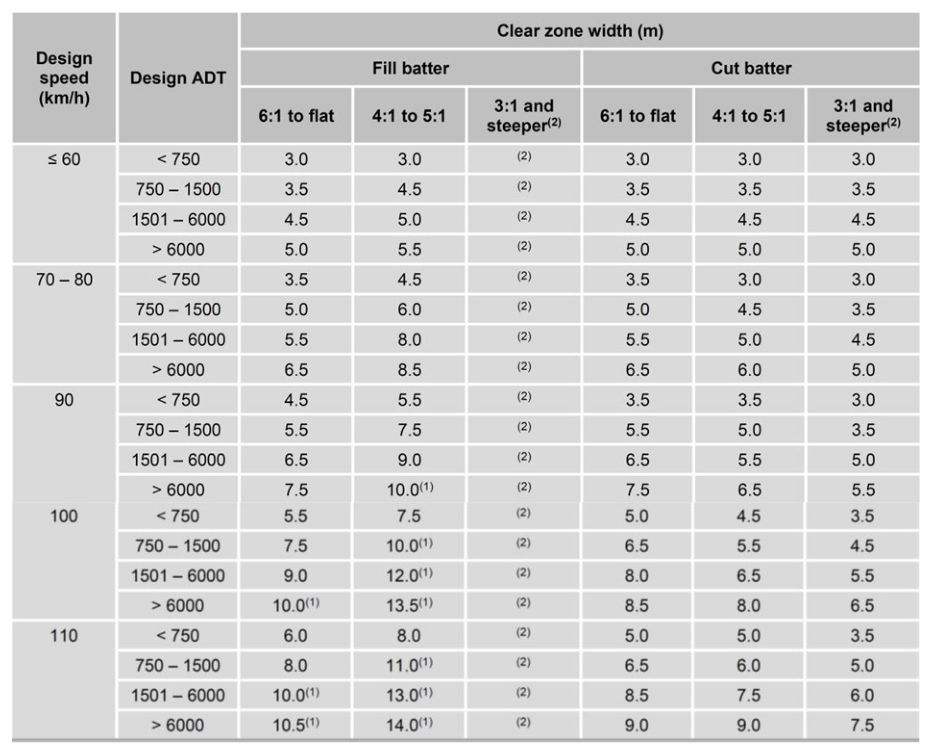
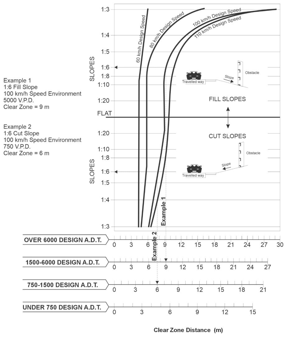
- Either Table 6.11.2 or Figure 6.11.2(b) may be used to establish the required clear zone distance for hazards located on straight roads, given a designated speed environment, AADT and the slope of the roadside.
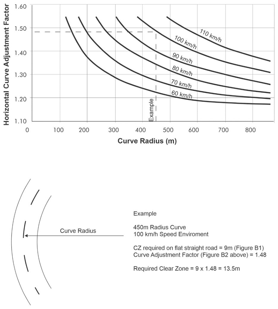
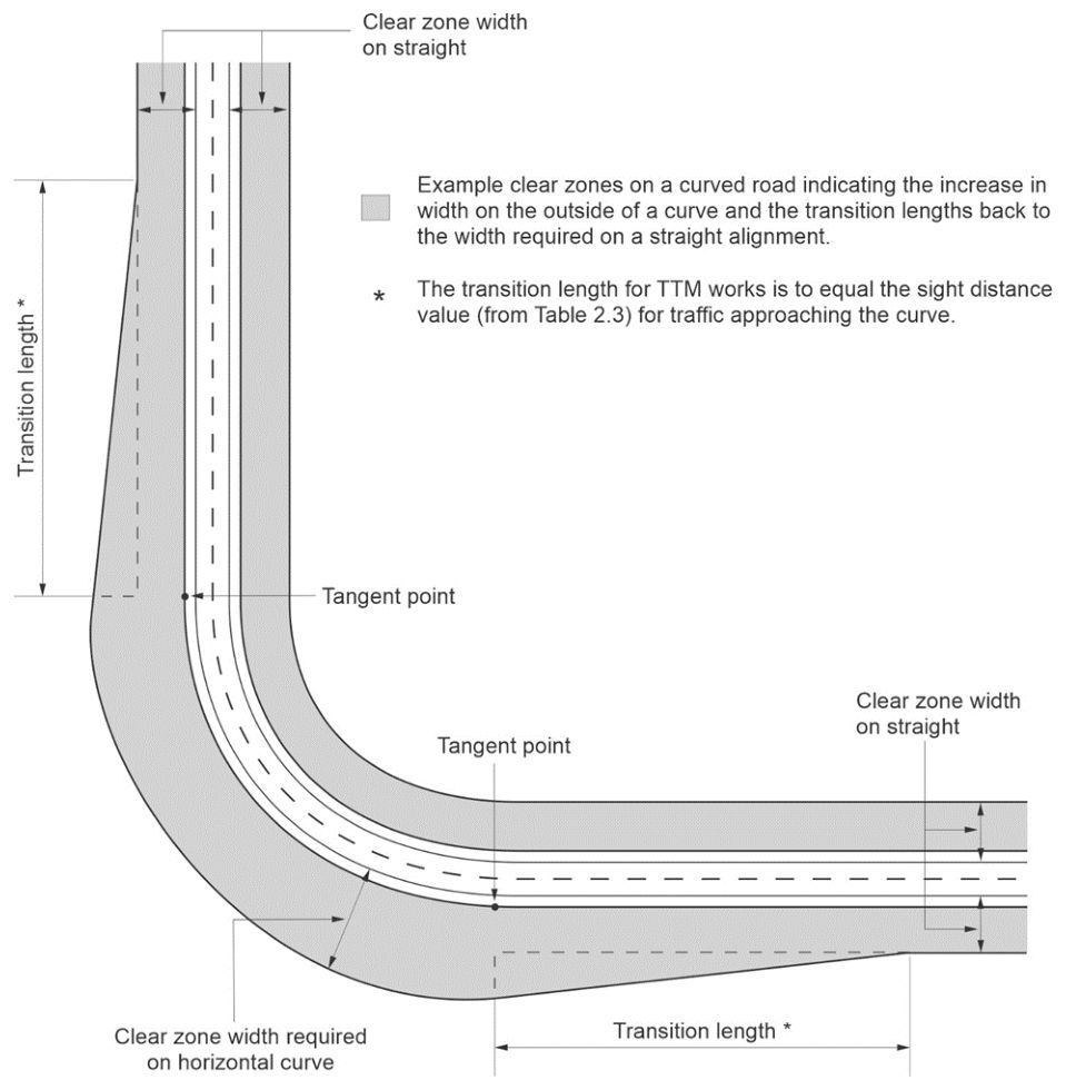
- A combination of Table 6.11.2 or Figure 6.11.2(b), and Figure 6.11.2(c) is used when the device is located on a curve in the road alignment. The horizontal curve multiplier established from Figure 6.11.2(c) recognises the higher risk and larger encroachment distance for errant vehicles on the outside of curved road alignments. See Figure 6.11.2(e) for transition requirements between the curve clear zone and the straight clear zone.
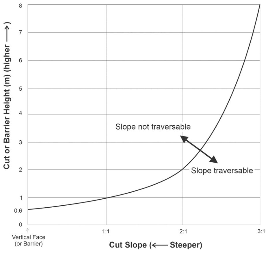
- A combination of Table 6.11.2 or Figure 6.11.2(b), and Figure 6.11.2(d) is used to assess the influence of cut height and slope on traversability when the device is located on a cut slope. Non-traversable cuttings typically prevent vehicles from travelling further away from the travel path and reduce the clear zone distance for other hazards beyond the cutting (as vehicles will not reach these hazards), However the non-traversable cutting may also be considered a hazard.
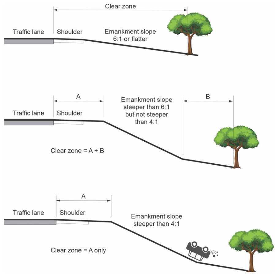
- Consideration of fill slopes. It may be necessary to approximate the contributory influence of each slope element in a roadside environment, noting that non-recoverable fill slopes are disregarded in the calculation of a clear zone. Typically, a vehicle will travel to the bottom of any non-recoverable fill slope and an errant vehicle recovery area beyond the toe of the non-recoverable fill slope will be required. See Figure 6.11.2(f) for fill slope examples.