𝐼2 = 1.6 𝐼𝑁#
Note that these fuses can carry 1.25 x the rated current (the non-fusing value) without rupturing.
HRC fuses are designated by their breaking range and utilisation category.
The first letter indicates the breaking range.
g full-range breaking capacity
a partial-range breaking capacity
The second letter indicates the utilisation category.
G general application
M motors
D time delay
N non-time delay
Typically gG fuselinks are used, those with a full-range breaking capacity for general applications.
The following is a typical set of time / current characteristic curves for the HRC family of gG fuses to AS/NZS 60269.1 taken from the Legrand 10 x 38 fuse data. They show the fusing times for various currents flowing through the fuse for each of the fuses in this part of the manufacturer's range.
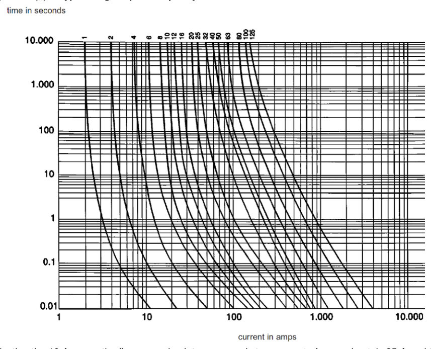
Selecting the 10 A curve, the five-second point corresponds to a current of approximately 25 A and the 0.4 second point corresponds to a current of approximately 44 A. Either fusing time may be used when fuses are selected as the protection device, but the time must be appropriate to the particular application.
Up to approximately 80 A, a smaller current is typically required to rupture a fuse at the 0.4 second disconnect time than for the Type C circuit breaker of similar rating.
When designing with fuses, the general rule of thumb is for the load current not to exceed 80% of the fuse rating to allow for inrush current; for example, a 20 A fuse should have a design load current no greater than 16 A.
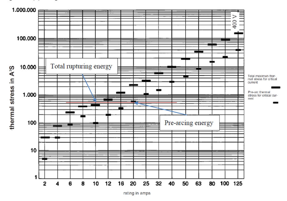
To provide discrimination between two fuses, the pre-arcing energy of the upstream device must be greater than or equal to the total fusing energy of the downstream device.
𝑃𝑟𝑒−𝑎𝑟𝑐𝑖𝑛𝑔 𝐼2𝑡 𝐹𝑢𝑝𝑠𝑡𝑟𝑒𝑎𝑚≥𝑇𝑜𝑡𝑎𝑙 𝐼2𝑡 𝐹𝑑𝑜𝑤𝑛𝑠𝑡𝑟𝑒𝑎𝑚#
As a general rule of thumb for fuses >8 A:
𝐹𝑢𝑝𝑠𝑡𝑟𝑒𝑎𝑚≥2 𝑥 𝐹𝑑𝑜𝑤𝑛𝑠𝑡𝑟𝑒𝑎𝑚
The following I²t characteristic shows the pre-arcing and total operating energy for the range of Legrand fuses described previously. For discrimination between two fuses, the pre-arcing I2t (shorter black line) of the upstream fuse must be greater than the total operating I2t (longer black line) of the downstream fuse; for example, a 6 A and 10 A will not discriminate but a 10 A and 20 A will.
Fuses for specific purposes can be manufactured to other standards; for example, the fast-acting 5 A, 5 x 20 mm fuses complying with IEC 60127 2 are used on the lamp control module of the traffic signal controllers. The following are the time / current curves for the fast acting fuses taken from the Littelfuse fuse data.
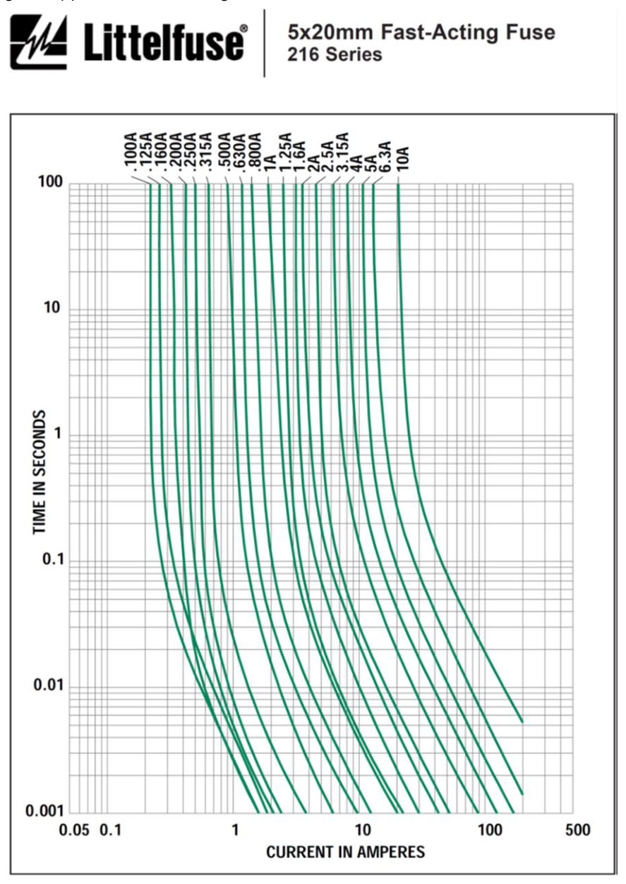
From these iT curves, for a 5 A fastblow fuse with a rupture time of 400 ms, a current of approximately 12 A is required.
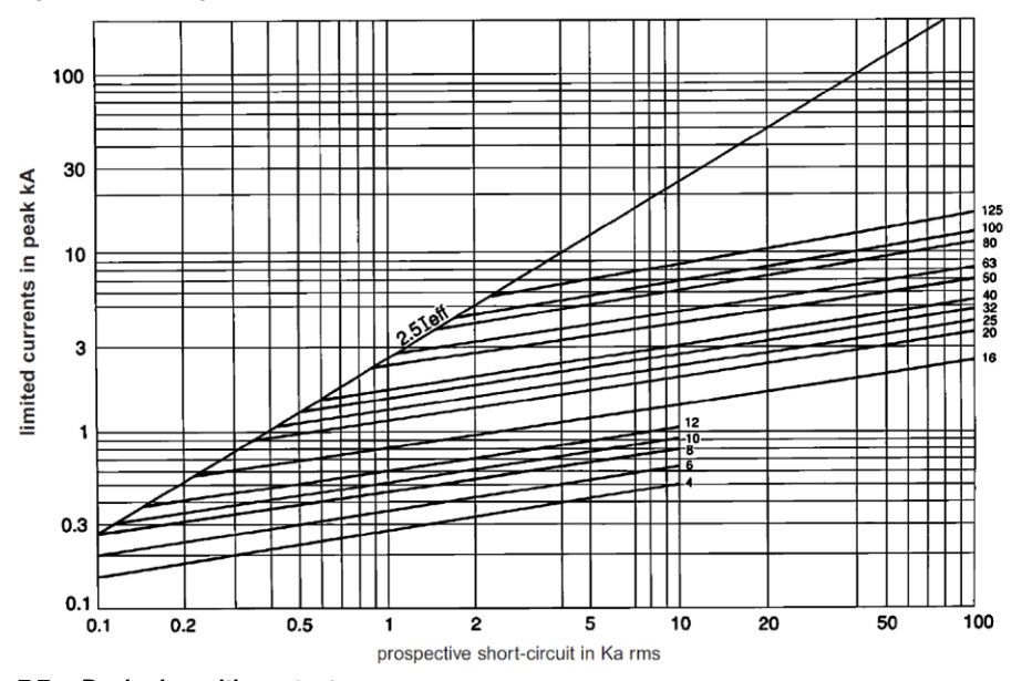
HRC fuse manufacturers will also provide current cut-off characteristics for their products. This is particularly useful in sizing the downstream equipment. For any short circuit current (X-axis), the peak let-through current is provided on the Y-axis for each fuse rating; for example, using a 40 A fuse with a 10 kA prospective short circuit current, the peak let-through current will be 3 kA.