6.8.3Surge protection device configuration#
6.8.3.1One port#
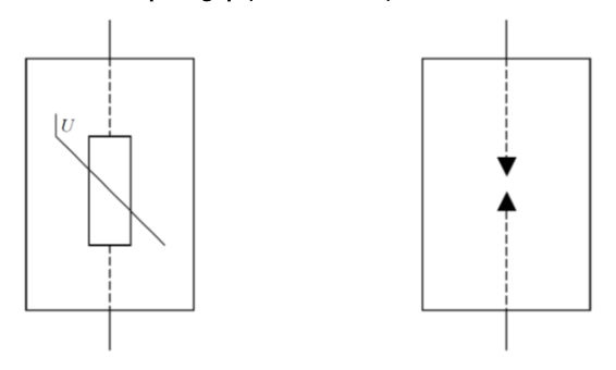
The following examples show typical one-port SPDs that are connected in shunt with the circuit to be protected. These devices do not affect the load current of the circuit being protected but their ability to clamp voltage is affected by voltage drop across the connecting leads.
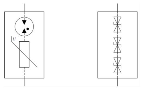
The following is an example of a one-port SPD with separate input and output terminals. This arrangement reduces the connecting lead voltage drop problem but requires the device to be able to carry the full load current.
6.8.3.2Two-port#
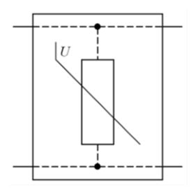
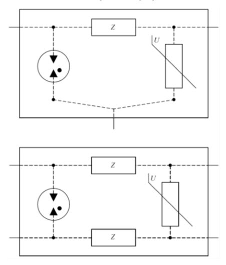
Two-port SPDs are connected in series with the circuit to be protected and insert a specific series impedance that has a current limiting effect. There is virtually no connecting lead voltage drop. Examples of three- and four-terminal two-port SPDs are:
6.8.3.3Multifunction#
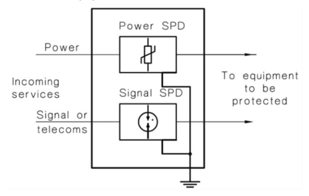
In addition to the single function SPDs mentioned previously, some devices combine both power and communications / signalling protection within the one device. This is an effective method to protect information technology equipment as the combined unit keeps the SPD earth connections very short, minimising the potential difference between the services when a surge strikes. The following diagram, from AS/NZS 1768, shows the typical configuration: