
6.14Installation of power surge protection devices#
The manufacturer’s instructions must be followed when installing an SPD.
For effective protection of equipment, it is critical that a good earthing / bonding system is implemented.
All services entering the installation should be in close proximity.
6.14.1Location#
6.14.1.1Main switchboard protection#
Primary protection is installed at the origin of the electrical installation or main switchboard.
Install SPDs after the main switch and prior to any RCD. Install between the actives and the neutral bar. Connection at the neutral bar should be as close as practicable to the MEN connection. Legibly and permanently label in accordance with AS/NZS 3000 Clause 2.9.5.1.
If there is sensitive equipment within the installation, the distance between the primary protection and the equipment to be protected is large, or if there are surge generators within the installation, secondary protection should be considered.
6.14.1.2Distribution board protection#
Secondary protection is installed at distribution boards (non-MEN). Install SPDs after the main switch and prior to RCDs. Install between the actives and the neutral bar and the neutral and the earth bar.
6.14.1.3Sub-circuit protection#
Tertiary protection is installed at sub-circuits and power outlets. Install SPDs after the circuit protection device and prior to any RCD. Where the protection device is an RCBO, consideration is required to the criticality of the downstream equipment as conduction of the SPD is likely to cause tripping of the RCBO.
6.14.1.4Specific equipment protection#
Specific equipment protection, in particular surge filters, can be installed at the equipment. Install the SPD in the circuit immediately upstream of the specific unit of equipment to be protected. Surge filters would normally be expected only where there is critical sensitive electronic equipment.
6.14.1.5Configuration#
Power equipment is generally more susceptible to damage from line-to-line or line-to-neutral than from line-to-earth. Where MEN (TN-C-S) system switchboards are installed, where the neutral is connected to the earth, good protection can be obtained by providing L-N protection. For other switchboards, L-N and N-E protection is recommended.
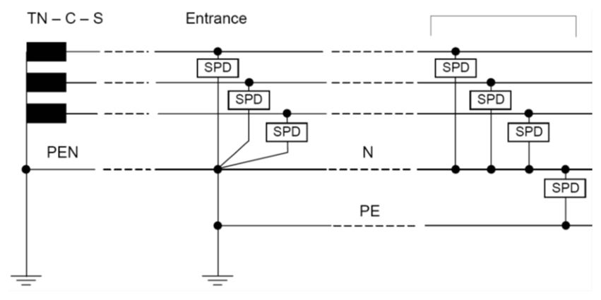
This figure is typical of the location and connection for SPDs for the MEN system. At the entrance, the SPDs are connected between the lines and the PEN conductor. At downstream switchboards, the SPDs should be connected L-N and N-E.
6.14.2Connection#
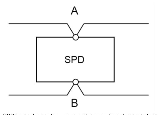
The following figure shows the preferred method for the connection of SPDs. Connecting conductors should be no less than 6 mm² for 50 kA devices, 16 mm² for 100 kA devices, between 300 mm-600 mm total length and there should be no loops in the conductor. Increasing the inductance of the conductor through length or coiling increases the voltage drop and reduces the effectiveness of the SPD. The MEN link length should not exceed 150 mm.
6.14.3Fusing#
Protection must be provided in case the SPD fails but it must not be so low that there is nuisance operation during a surge current diversion.
Primary and secondary SPDs require fuse or circuit breaker protection. Refer to manufacturer’s recommendations for specific SPDs. As a rule of thumb, the following may be used:
| I max | Cable | HRC fuse | MCB |
|---|---|---|---|
| 100 kA | 16 mm² | 63 A | 63 A type D |
| 50 kA | 6 mm² | 32 A | 32 A type D |