7.9Designing with an uninterruptible power supply#
Essential electrical equipment will often require a continuous, unbroken power supply. To achieve this, the UPS will be installed upstream of the critical equipment. The following is an example of principles that should be considered when designing for the UPS supply to a traffic signal controller.
Because traffic signals are a safety system, electrical faults must be cleared quickly; however, the UPS is not an infinite bus. It is limited in how much fault current it can provide economically.
The following circuit breakers are installed in the Eclipse controller switchboard:
- 20 A for the lamp modules
- 16 A for the flash supply
- 16 A for the auxiliary
- 10 A for the logic board, and
- 10 A for the detector card.
Each of the field wiring 240 V active cores is protected by a 5 A fuse which requires up to 14.5 A fault current to clear in 400 ms.
Because of pedestrian pushbuttons located on the posts, the public is more likely to come into contact with a traffic signal post than the controller, and the possibility of a cable becoming disconnected from terminal in a post during a vehicle incident can be high; therefore, it is more important to ensure that faults occurring in the field wiring / posts are cleared quickly when on UPS supply.
Shutdown of the UPS due to a major fault within the controller is considered acceptable as an uneconomically large UPS would be required to provide the required fault current.
The lanterns should be LED to minimise the load requirements on the protection devices.
The following parameters are important when considering the use of a UPS:
- load current demand of all devices including the controller and lanterns
- Impedance of supply cable from the UPS to the controller
- Impedance of multicore cable
- available fault current
- UPS battery run time, and
- UPS battery charge time.
The following is an example of power consumption loads for an average intersection (the specific parameters will need to be determined for specific installations):
- Multicore Run 1 load 123.3 W
- Multicore Run 2 load 155.8 W
- Eclipse controller load 41.5 W
- Total controller and lantern load 320.6 W
Assuming a 0.9 power factor:
Load in V A = 320.6 / 0.9 = 356 V A
Load in amps = 356 / 230 = 1.55 A
The Novus FXM UPS 2000 W / VA system has been tested by Transport and Main Roads with the following performance characteristics recorded following:
- UPS internal impedance: 6.2 Ω
- Prospective short circuit current at UPS terminals @ 230 V: 37 A
- Maximum circuit impedance to clear a 5 A fastblow fuse within 400 ms: 16.5 Ω
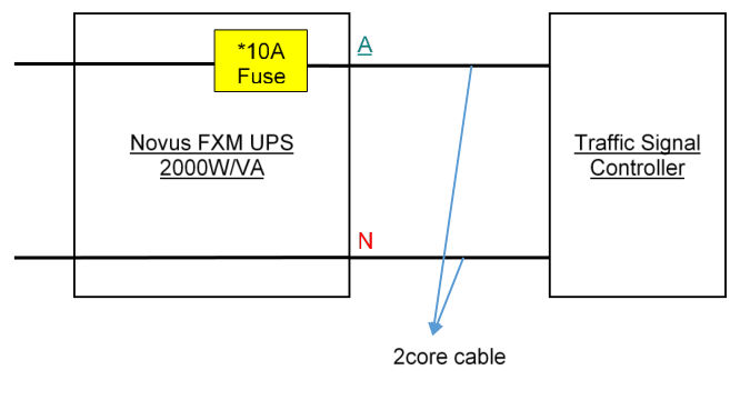
The UPS output to the controller must be protected by a 10 A Littlefuse – POWR KLK Series 10 x 38 – part No. 0KLK010.T.