7.13.7Continuing with earth fault loop Impedance#
The scope of AS/NZS 3000 includes the provision of minimum standards to protect persons from electric shock. One method to protect against dangers that may arise from contact with exposed conductive parts that may become live under fault conditions (indirect contact) is by the automatic disconnection of supply. This is covered in Clause 1.5.5.3 of AS/NZS 3000.
EFLI is an integral part of protection against indirect contact by the automatic disconnection of supply along with touch voltage limits and disconnection times.
To summarise the requirements:
- If an active-to-earth fault occurs that could cause the voltage on an exposed conductive part to exceed 50 V ac, a protective device must automatically disconnect the source of supply.
- The characteristics of the circuit protection and the EFLI must allow the protection device to disconnect the fault current within the specified time.
- The maximum disconnection time is 0.4 s for final sub-circuits to socket outlets, and five seconds for other circuits where it can be shown that people are not exposed to touch voltages that exceed safe values.
When an active-to-earth fault occurs in an electrical system, it is imperative that the fault is cleared automatically within the required disconnect time to minimise any body current that could flow, should an individual be in contact with an earthed part of the system.
The current / time characteristic of the particular fuse or circuit breaker protecting the circuit will provide the current required to clear the fault within the required disconnect time.
Ohm's Law then provides the maximum circuit impedance that will allow this clearing current to flow.
When an active-to-earth fault occurs, the impedance of the circuit around which the fault current flows limits the prospective fault current. This impedance is referred to as the EFLI. This impedance needs to be sufficiently low so that it allows a high enough current to flow around the circuit and clear the protection device within the required disconnect time.
It is imperative to know:
- the path of the fault current, and
- the impedance of that path.
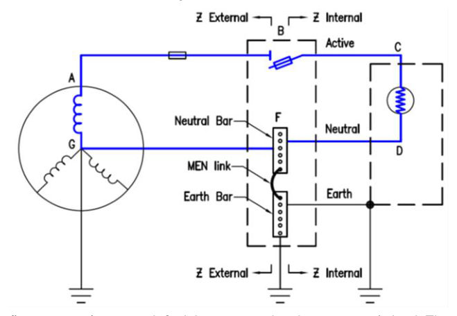
The following generalised circuit shows the typical current path for a healthy circuit. The current flows from the transformer through the Electricity Entity’s active network of protection and distribution cabling to the point of supply. From the point of supply, the current flows through the active consumers’ mains, submains, sub-circuits and protection to the load. After doing its useful work, the current returns through the neutrals to the point of supply and through the Electricity Entity neutrals to the transformer, thus completing the circuit. This is the path A-B-C-D-F-G.
The impedance of the Electricity Entity network is Zext and that of the consumer’s network Zint.
In the following figure, an active-to-earth fault has occurred at the consumer’s load. The majority of the fault current flows through the path A-B-C-H-I-J-F-G (note that the current starts from the transformer and must return to the transformer for there to be a circuit; this path is the worst case path but it can be readily calculated).
In the real-life MEN situation, the earth stakes are part of the circuit for the fault current so some current may run in a parallel path through I-K-L-J-F-G or I-K-L-M-G or I-J-L-M-G or through multiple other paths that are part of the MEN system. The current paths and current magnitude will depend on the relative resistances of the various paths available; hence, the return path of the fault current will generally have an impedance less than the worst case as there are multiple return paths in parallel.
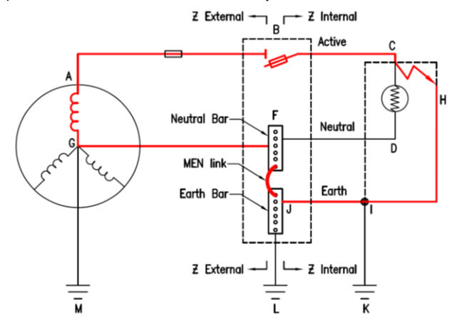
The fault current circuit path comprises the external impedance Zext and the internal impedance Zint.
Take for example, a 32 A type C circuit breaker. This has a 7.5 x multiplier for the 400 ms disconnect time; therefore, the current required to trip the breaker is 32 x 7.5 = 240 A.
By Ohm’s Law
R = V / I = 230 / 240 = 0.96
This is the maximum impedance of the complete circuit (A-B-C-H-I-J-F-G shown) that will allow sufficient current to flow around the entire circuit and allow the circuit breaker to trip in the 400 ms disconnect time.
AS/NZS 3000 Clause 8.3.3 includes verification of impedance required for automatic disconnection of supply as a mandatory test. While preliminary tests may be carried out prior to circuit energisation, Transport and Main Roads requires full EFLI tests and a recording of those results, once the circuit has been energised.
Required tests are:
- at the switchboard to measure Zext, and
- at the last pole / post on a run to measure Ztot.
When regular maintenance is carried out, any changes in the impedance tests can then be isolated to either the internal circuit or the Electricity Entity network.