6.5How surge protection devices work#
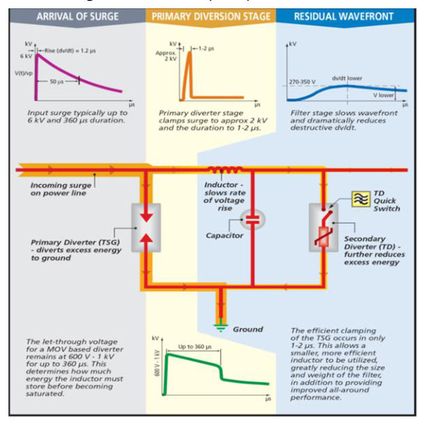
In the absence of surges in a power system, the SPD does not have a significant influence on the operational characteristics of the system where it is installed. During a surge in the power system, the SPD responds by lowering its impedance, diverting the surge current through it, to limit the voltage to its protective level. After the surge, the SPD recovers to a high impedance state. In the spark gap-type technologies, the electrodes and gas between the electrodes are designed to turn on and direct the surge energy to earth. Conventional SPD technologies use either or both metal oxide varistors (MOVs) and silicon avalanche diodes (SADs) to limit the effects of surges; however, if the device is required to constantly conduct due to normal mains overvoltages, it can overheat and fail or possibly cause a fire. The UL 1449 testing standard requires that the device is safe under both temporary and abnormal overvoltages. Many manufacturers use a gas discharge tube (GDT) in series with the MOV to extend the working voltage of their products. The MOVs only conduct once the upstream GDT conducts. This enables the MOVs to be out of circuit for the majority of the time and, consequently, they are not degraded by normal mains overvoltage. In critical applications such as electronic equipment, surge reduction filters (SRFs) are used as finer protection. These are typically located close to the equipment to be protected. SRFs reduce not only the amplitude Up of the surge but also the dv / dt of the surge which can damage the equipment. The following figure shows a typical surge reduction filter and its smoothing operation: