
6.16Telecommunications#
Many of the principles stated previously relating to power system SPDs are directly applicable to telecommunications systems. Standards compliance must meet IEC 61643 21 and/or UL 497B as appropriate.
6.16.1Determining need for communications surge protection devices#
The factors which will assist the assessment of the likelihood of lightning overvoltages occurring at a telecommunications installation and the need for protection are (from AS4262 Parts 1 and 2):
6.16.1.1Known lightning damage / injury history#
Known damage to telecommunication facilities within a radius of 500 m with similar geographical features to the location under consideration is considered high risk.
6.16.1.2Thunderdays per year#
A number >40 indicates high risk.
6.16.1.3Building density#
The number of buildings within 100 m of the location under consideration provides a measure of the number of connections to earth. A number <5 indicates higher risk.
6.16.1.4Soil resistivity#
The higher the soil resistivity, the greater the area of influence of a lightning strike to ground. Soil resistivity >1000 Ω / m is high risk.
6.16.1.5Exposed terrain#
Elevated locations over 1000 m above sea level or prominences in the terrain, such as clifftops, ridges, bluffs and hills are considered high risk.
6.16.1.6Building construction#
Concrete slab and metal frame construction constitute an earthed environment. This increases the probability that a person is in direct or indirect contact with the local earth and hence at higher risk when using the telecommunication facility during an electrical storm.
6.16.1.7Aerial telecommunication cable construction#
A service fed by cable containing more than 200 m of aerial cable within approximately 2 km of the location is considered to be at high risk.
6.16.1.8Isolated telecommunications service#
A service located in a structure that is not connected to any public electricity supply system or where the public electricity supply power earth is greater than 100 m from the building housing the telecommunication facility is considered high risk.
6.16.1.9Equipment cost#
High replacement cost of the equipment compared to the cost of the protection system for that equipment is considered high risk.
6.16.1.10Equipment necessity#
The nature of the equipment being protected and how critical its operation is to the user determine the risk. If the equipment is critical and its loss not acceptable, it is considered high risk. Protection should be installed for any condition constituting high risk. If protection is required, it should be installed at the entry to the installation which should be close to the main switchboard. Secondary surge suppression for the protection of equipment is normally provided close to the equipment.
6.16.2Selecting a communications surge protection device#
The selection of the appropriate SPD for telecommunications and signalling networks depends on the particular equipment to be protected, the signalling protocol and the following:
- maximum continuous operating voltage Uc
- voltage protection level Up
- maximum line current IL
- leakage current between the terminals
- frequency of system operation, and
- connector type and/or impedance.
When installed in the circuit, the characteristics of the SPD can affect the transmission characteristics of the network. The parameters that may be affected are:
- capacitance
- series resistance
- insertion loss
- return loss
- longitudinal balance, and
- near end cross-talk.
Typically the telecommunications equipment and protocol will define the characteristics of the SPD. There may only be a need to specify the type of physical connection, the number of lines to be protected or its surge rating.
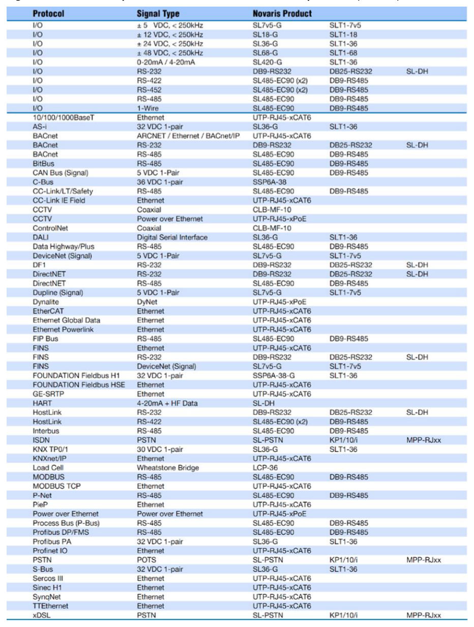
Equipment user manuals will sometimes have information on specific SPD requirements, where no internal protection is provided and may also provide the equipment voltage withstand level. SPD manufacturers will typically design products for specific telecommunications applications. This makes selection of the product easier. As an example only, Novaris provides the following table for suitable products for the various communications protocols:
6.16.3Installation of communications surge protection devices#
Primary surge suppression for the protection of end users is installed at the entry to the structure between the telecommunications line conductors and earth. The communications main distribution frame and the main switchboard should be located close together to enable the earthing / bonding of surge suppression devices. A total earthing conductor (minimum 6 mm²) length of 1.5 m is preferred and should not exceed 10 m between the surge protection device and the earthing bar of the main switchboard.
For telephone and signalling lines, a three terminal gas SPD is often used as the primary protection for both common and differential mode transients. A gas arrester typically provides protection against the L-E transients. Additional L-L protection can be provided if required by using a solid state device such as a varistor.
Secondary surge suppression for the protection of equipment is normally provided close to the equipment. The earth conductor should be of minimum cross-sectional area 2.5 mm² and maximum length 1.5 m.
The provision of primary and secondary protection must be correctly coordinated so they function correctly. The primary protection is generally able to handle large surge currents, but may be slow to operate, and therefore can let relatively high transients through during the operation time. The secondary stage is usually rated to handle lower energy levels, but is fast to operate. In this manner, it is able to effectively absorb and clamp the residual transient energy let through from the primary protection. Generally, for these two protection stages to function correctly, an interposing impedance needs to be present and this may be the interconnection cable or, more reliably, a deliberate impedance placed within either protection stage.
When the secondary protection is provided within the equipment to be protected, the supplier should be contacted to determine if primary protection is required.
Telecommunications equipment may be subjected to both mains overvoltage and overvoltages within the telecommunications network so surge protection on both systems may be required.
Where cable is provided between two structures, surge suppression should be installed at the entry to both structures.
For mains powered telecommunications equipment, a Multiservice Surge Protective Device (MSPD) is, in terms of suitability, cost and ease of installation, one of the best ways of reducing the risk of damage. These combination units are located immediately adjacent to the equipment being protected and have the distinct advantage of ensuring that the connection between the mains earth and the telecommunications SPD earth is kept very short. To provide the best protection possible, all interconnected equipment (for example, computer, modem and printer) must be connected to the same MSPD.
While shunt protection provides a certain level of transient protection, it does not attenuate the rate of rise of voltage up to the clamp voltage of the device. This fast rate of rise of voltage (dV / dt) causes a variety of problems in computing, communications, instrumentation and other electronic equipment. The use of a suitably designed low pass filter following the shunt diverter will both reduce the peak let-through voltage and reduce the rate of rise of that voltage to levels which the connected equipment can tolerate. This protection option is usually packaged in the one unit which includes both the shunt protection and the filter.