7.13.6Relationship between body current parameters#
The relationship between body current and the time that current can flow so that cardiac arrest and organic damage to the body is not likely to occur, the body impedance at various voltages, the touch voltage and the times required to disconnect a circuit for two touch voltages has been discussed. Referring to Table 7.13.6(a), using 50% of the population and a 20% derating for current path hand to foot, the body impedance at a touch voltage of 50 V ac is 2000 Ω and at 100 V ac is 1380 Ω. Using Ohm's Law, the prospective body currents at touch voltages of 50 V and 100 V can be found.
For a touch voltage of 50 V, the prospective body current is:
I = V / R = 50 / 2000 = 25 mA
And for a touch voltage of 100 V, the prospective body current is:
I = V / R = 100 / 1380 = 72 mA
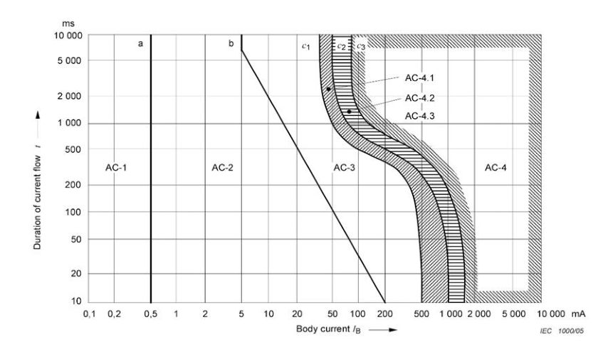
Referring to Figure 7.13.5, the maximum permissible duration of a 50 V ac touch voltage is five seconds and for a 100 V ac touch voltage, 400 ms.
These parameters are tabulated here:
| Voltage (v) | Time (s) | Body impedance hand to foot (Ω) | Current (mA) |
|---|---|---|---|
| 50 | 5 | 2000 | 25 |
| 100 | 0.4 | 1380 | 72 |
When these two points for time and current corresponding to the touch voltages of 50 V and 100 V are plotted on the body current against time chart, both points are located within the AC-3 area below the c1 line; hence, when designs are carried out in accordance with these parameters, it can be expected that the electrical installation would have no permanent detrimental effect on the typical person, should the person be unfortunate enough to be in contact with the installation at a time a fault occurs.
However, these calculations are based on a number of parameters that can vary widely, for example the pathway of current through the body, the moisture of the skin and hence the skin impedance, and the surface area of contact.
While fuses and circuit breakers are designed to provide overcurrent and short circuit protection for electrical components, RCDs have been designed for personnel protection (the 6 mA, 10 mA and 30 mA values) and the 100 mA, 300 mA and 500 mA ratings minimise the potential of leakage current generating heat and the possibility of fire.
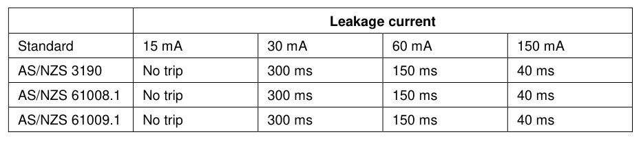
The following table provides the maximum values of break times for a standard 30 mA RCD according to the various Standards:
| Standard | 15 mA | 30 mA | 60 mA | 150 mA |
|---|---|---|---|---|
| AS/NZS 3190 | No trip | 300 ms | 150 ms | 40 ms |
| AS/NZS 61008.1 | No trip | 300 ms | 150 ms | 40 ms |
| AS/NZS 61009.1 | No trip | 300 ms | 150 ms | 40 ms |
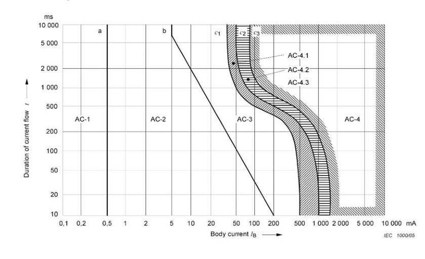
The 30 mA RCD leakage current and maximum break times have been plotted on the time/current characteristics points of AS/NZS 60479.1 (see Figure 7.13.6(b)) for the 30 mA, 60 mA and 150 mA leakage currents).
The c1 curve of AS/NZS 60479.1 is the threshold before serious physiological effects are to be expected. RCDs have been designed such that the time / current activation points are much closer to the curve b than the curve c1 requiring tripping to be in the area where there should be less harmful effects, should the leakage current pass through the body. As the plotted times are maximum values, it is expected that the typical average operating times will be less, bringing the points closer to the AC-2 region.