
6.12Design considerations#
When designing with surge protection, the following need to be considered:
6.12.1Area boundary#
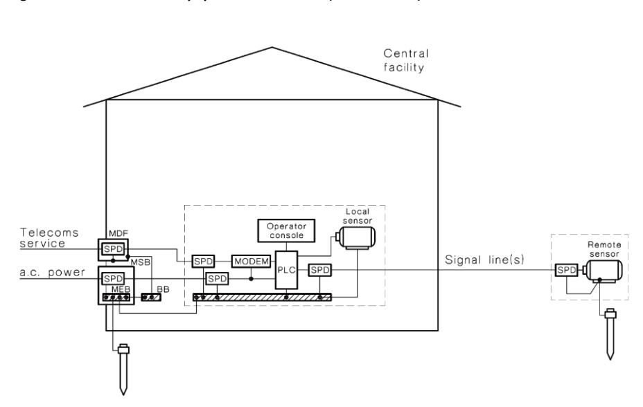
Determine the boundary around the equipment that needs to be protected. Wherever a copper line crosses the boundary, consideration should be given to the installation of the SPD. The following figure from AS/NZS 1768 illustrates the boundaries around equipment to be protected:
6.12.2Surge rating#
Primary protection to transfer the bulk of the transients to earth is generally located at the entry to an installation while secondary protection is provided closer to the specific equipment to be protected. The location and type of SPDs installed will depend on the risk of surges and the type of equipment to be protected.
The maximum surge current specified in the British and American standards is 10 kA with a maximum of 70 kA in the Australian Standard. Some surge protection devices are rated at 200 kA. The reason is life and reliability, particularly for MOVs, as each surge causes a small amount of degradation in the MOV; for example, one particular type of MOV can withstand: (EPCOS SIOV Metal Oxide Varistor Data Book 2001)
- 1 x 40 kA surge
- 10 x 15 kA surges
- 100 x 5 kA surges
- 1000 x 2 kA surges
- 10,000 x 500 A surges
- 100,000 x 200 A surges
So in a high surge area, the higher rated MOV is specified, not for current handling capacity, but for reliability. The recommended surge rating for power SPDs (Imax) depends on where they are installed. The following table provides guidance:
| Category | Surge protection device location | Lightning risk exposure | ||
|---|---|---|---|---|
| High | Medium | Low | ||
| C3 | Service entrance, structure in high lightning area or fitted with lightning protection system | 100 kA | 65 kA | 65 kA |
| C2 | Service entrance, structure with long overhead lines, large industrial or commercial premises | 70 kA | 40 kA | 40 kA |
| C1 | Service entrance, other than C3 and C2 | 40 kA | 20 kA | 15 kA |
| B | Major submains, load centres, short final sub-circuits | 20 kA | 20 kA | 5 kA |
| A | Long final sub-circuits, electricity supply outlets | 10 kA | 5 kA | 3 kA |
Table in words
- For category C3, service entrance, structure in high lightning area or fitted with lightning protection system, the recommended Imax surge rating is 100 kA for high lightning risk exposure, 65 kA for medium lightning risk exposure and 65 kA for low lightning risk exposure.
- For category C2, service entrance, structure with long overhead lines, large industrial or commercial premises, the recommended Imax surge rating is 70 kA for high lightning risk exposure, 40 kA for medium lightning risk exposure and 40 kA for low lightning risk exposure.
- For category C1, service entrance, other than C3 and C2, the recommended Imax surge rating is 40 kA for high lightning risk exposure, 20 kA for medium lightning risk exposure and 15 kA for low lightning risk exposure.
- For category B, major submains, load centres, short final sub-circuits, the recommended Imax surge rating is 20 kA for high lightning risk exposure, 20 kA for medium lightning risk exposure and 5 kA for low lightning risk exposure.
- For category A, long final sub-circuits, electricity supply outlets, the recommended Imax surge rating is 10 kA for high lightning risk exposure, 5 kA for medium lightning risk exposure and 3 kA for low lightning risk exposure.
where High >2 lightning strikes / km² / yr Medium 0.5–2 lightning strikes / km² / yr Low <0.5 lightning strikes / km² / yr
6.12.3Protection characteristics#
The characteristics of the SPD must be appropriate for the equipment to be protected. The values of Uc, In, Imax and Up describe the characteristics of the SPD in relation to its electrical operating environment and its ability to function as required. The voltage protection level of the SPD must be less than the equipment withstand voltage and hence, the lower the UP value, the better the protection; however, the value is limited by the maximum continuous operating voltage and temporary overvoltages expected on the system.
An important aspect in selecting the SPD is its voltage limiting performance during the expected surge event. SPDs with a correctly selected low limiting voltage will protect the equipment. SPDs with a high energy withstand may only result in a longer operating life of the SPD.
6.12.4Protection distance#
The distance between the SPD and equipment to be protected should be as short and straight as practicable, and not greater than 10 m. Long and curved paths introduce inductance into the line increasing the dv/dt.
6.12.5Prospective life and failure mode#
The prospective life of the SPD depends on the probability of occurrence of surges exceeding the maximum discharge capability of the device. Imax rating should be appropriate for the location in which the device is to be installed. In is an indication of the life of the device.
Failure to short circuit should cause the circuit protection device to open. Failure to open circuit should put a high impedance in the circuit. In both cases, an indication should be provided that the SPD is no longer functioning.
6.12.6Interaction with other equipment#
Under normal and fault conditions the SPD should not interfere with other circuit devices. When conducting a surge at the nominal discharge current, the circuit protective device must not operate. Refer to manufacturer for fuse and circuit breaker requirements for specific SPDs.
6.12.7Coordination with other surge protection devices#
For coordination of SPDs, the energy dissipated by the downstream device must be less than or equal to its maximum energy withstand for all values of current up to Imax at the upstream SPD.
Often it is assumed that the peak let-through voltage of the primary protection is sufficiently low so as not to damage any secondary protection. While coordination is complex, a simple rule of thumb is to ensure that there is 10–20 m of cabling between the primary and secondary protection as this will provide additional attenuation for the surge.