7.10Designing for cable current carrying capacity#
7.10.1Cable materials#
A simple cable consists of a metallic conductor, typically copper or aluminium, surrounded by an insulating layer, typically PVC or XLPE, and covered with a protective outer sheath, typically PVC.
When a current passes through the conductor, heat is generated due to the conductor’s resistance according to the i²R law. This heat must be dissipated through the insulation and sheath into the material surrounding the cable; for example, heat will be transferred more rapidly away from a cable directly buried in the ground than from a cable installed in thermal insulation in a ceiling cavity because the ground is a better heat sink than the insul fluff.
The heat flow must be such that the temperature of the insulation does not reach a level where the material begins to degrade; therefore, the heat generated by the current flowing in the conductor and the heat dissipation rate due to the installation method must both be considered by the cable manufacturer when the cable current rating is being determined.
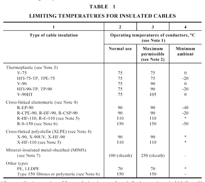
The different cable insulation materials are rated for particular maximum temperatures; for example, thermoplastics such as PVC have a rating of 75°C while XLPE is rated at 90°C. Sustained operation of the cable above these ratings will result in degradation of the insulation.
AS/NZS 3808 provides the material types, abbreviations and some information on the common materials used for the insulation and sheath of electric cables.
Standards such as AS/NZS 3008.1.1 provide the maximum current that particular cables can sustain safely for different installation methods.
7.10.2Standard installation conditions#
AS/NZS 3008.1.1 provides standard installations for:
- cables installed in air (Clause 3.4.2)
- cables installed in thermal insulation (Clause 3.4.3)
- cables buried direct in the ground (Clause 3.4.4), and
- cables installed in underground wiring enclosures (Clause 3.4.5).
For cables installed underground in conduit, the following are the standard conditions:
- Ambient soil temperature 25⁰C.
- depth of centre of conduit from ground surface 500 mm.
- soil thermal resistivity of 1.2⁰C.m / W, and
- multicore cable in a single wiring enclosure.
7.10.3Derating factors for non-standard installation conditions#
Where the installation conditions are not in compliance with the standard conditions, derating factors must be applied to ensure that the temperature of the conductor does not rise to a temperature greater than the maximum temperature the conductor insulation can withstand when carrying the full rated current. These are found in AS/NZS 3008.1.1.
| Clause | Derating factor | C | Table |
|---|---|---|---|
| 3.5.2 | derating factors for groups | C1 | Tables 22–26 |
| 3.5.3 | derating factors for ambient temperature | C2 | Table 27 |
| 3.5.4 | derating factor for depth of laying | C3 | Table 28 |
| 3.5.5 | derating factor for soil thermal resistivity | C4 | Table 29 |
| 3.5.6 | derating factor for varying load | C5 | |
| 3.5.7 | derating factor for thermal insulation | C6 | |
| 3.5.8 | derating factor for direct sunlight | C7 | |
| 3.5.9 | derating for harmonic currents | C8 |
Where non-standard installation conditions apply, the derated value for IN must be used:
IN = C1 × C2 × C3 × C4 × C5 × C6 × C7 × C8 × IZ
where
IN = rated current of the protection device
Where the particular derating factor is not applicable, the C value is taken as 1.
7.10.4Cable protection#
Appropriate selection of the cable protection device, whether fuse or circuit breaker, will protect the cable by limiting the current flow so that the requirements of the Standards can be met and the cable insulation will be protected from heat degradation.
For continuous operation of the circuit, the maximum demand current must be less than the nominal operating current of the protection device. Otherwise, the protection could activate and open the circuit; hence, the maximum demand current (IB) must be less than or equal to the rated current of the protection device (IN) which also must be less than or equal to the continuous current carrying capacity of the cable (Iz). Or:
IB ≤ IN ≤ IZ
A second requirement is that the current ensuring effective operation of the device (I₂) must be less than or equal to 1.45 x the continuous current carrying capacity of the cable (Iz). Or:
I₂ ≤ 1.45 Iz
where
- IB
- maximum demand current of the circuit
- IN
- rated current of the protection device
- Iz
- continuous current carrying capacity of the cable
- I₂
- current ensuring effective operation of device
The current ensuring effective operation of the device (the current required to trip the breaker or rupture the fuselink) is different for each of the two devices as the design of breakers and fuses is based on different principles.
For circuit breakers up to 63 A:
I₂ = 1.45 IN
But
I₂ ≤ 1.45 Iz
I₂ ≤ 1.45 IN
I₂ ≤ 1.45 Iz
Therefore, where circuit breakers are used for protection the overall requirement is:
IB ≤ IN ≤ Iz
For fuselinks up to 63 A:
I₂ = 1.6 IN
But
I₂ ≤ 1.45 Iz
1.6 IN ≤ 1.45 Iz
IN ≤ 0.9 Iz
Therefore, where fuses are used for protection the overall requirement is:
IB ≤ IN ≤ 0.9 Iz
7.10.5Cable operating temperature#
The cable parameters included in AS/NZS 3008.1.1 are based on standard operating conditions for the specified type of cable and installation methods and typically allow for the cable carrying the full load current; however, many cables within Transport and Main Roads installations are not operating at the full load current. Designs must be carried out using the appropriate conductor temperature, based on the current the cable will be carrying.
Referring to AS/NZS 3008.1.1, an accurate calculation of conductor temperature can be made using the following equation:
(θO − θA) / (θR − θA) = (IO / IR)²
where
- IO
- operating current in amps
- IR
- cable rated current in amps (AS/NZS 3008.1.1 Tables 4 to 21)
- θO
- operating temperature of cable in °C when carrying current IO
- θR
- operating temperature in °C when carrying IR (AS/NZS 3008.1.1 Table 1)
- θA
- ambient air or soil temperature in °C
= under rated conditions
40°C for air
25°C for ground
Rearranging
θO = θA + (θR − θA) (IO / IR)²
The calculated temperature θO is then raised to the nearest temperature 45°C, 60°C, 75°C and so on for use with Tables 34 to 51 to determine the cable ac resistance and voltage drop.
Examples#
Consumers’ mains cable temperature rating should be determined depending on the size of the cable selected and its maximum demand. The conservative temperature would be 75°C.; however, a 4 c 25 mm² cable would be expected to run at 48°C and a 2 c 16 mm² cable would be expected to run at 53°C if operating at 64 A (80% of the 80 A fuse rating).
Road lighting specified submains and sub-circuit cabling will not be carrying the maximum cable design load.
For the standard 16 mm² and 25 mm² XLPE / PVC submains cables installed in underground conduit, with operating current equal to 80% of the protection rating and standard conditions, the cable operating temperatures are calculated to be:
| Fuse size (A) | Single phase cable (T°C) 16 mm² | Single phase cable (T°C) 25 mm² | Three phase cable (T°C) 16 mm² | Three phase cable (T°C) 25 mm² |
|---|---|---|---|---|
| 20 | 26.7 | 26.0 | 27.5 | 26.5 |
| 25 | 27.7 | 26.6 | 29.0 | 27.3 |
| 32 | 29.4 | 27.6 | 31.5 | 28.7 |
When designing for voltage drop and EFLI for submains cables under these conditions, the 75°C cable data should be used.
7.10.6Resistance change with temperature#
As temperature increases, the conductivity of metallic materials decreases with the corresponding increase in resistivity. As resistance is related to resistivity by:
R = ρ L / S
where
- R
- resistance of conductor (W)
- ρ
- resistivity at temperature T (W mm² / m)
- L
- length of conductor (m)
- S
- cross-sectional area of conductor (mm²)
it follows that the resistance of a metallic conductor also rises with temperature.
Thermal changes of resistivity can be calculated using the following formula:
ρ = ρ₀ (1 + α (T − T₀))
where
- ρ
- resistivity at temperature T (W mm² / m)
- ρ₀
- resistivity at reference temperature T₀ (W mm² / m)
- α
- temperature coefficient of resistivity (°C-1)
For commercial copper at 20°C
ρ₀ = 1.7241 x 10⁻² Ω mm² / m
α = 0.00393°C-1
T₀ = 20°C
Therefore
ρ = ρ₀ (1 + α (T − T₀))
= 1.7241 x 10⁻² (1 + 0.00393 (T − 20))
At 75°C
ρ = ρ₀ (1 + α (T − T₀))
= 1.7241 x 10⁻² (1 + 0.00393 (75 − 20))
= 2.097 x 10⁻² Ω mm² / m
When designing with conductors that are lightly loaded and overrated for current carrying capacity, the formula in Section 7.10.5 Cable operating temperature can be used to determine the approximate cable operating temperature.
When circuit testing is being carried out, particularly on lightly loaded conductors, a more realistic maximum impedance value can be obtained for reference by calculating the resistivity at 25°C.
At 25°C
Therefore the measured value of EFLI should be 0.8384 of the maximum values at 75°C included in Table 8.1 of AS/NZS 3000.
7.10.7Cable selection for current carrying capacity#
Generally, once the maximum demand of the circuit is determined, the next larger standard fuse or circuit breaker is selected and then the cable is chosen that has a rating equal to or larger than the protection size, taking into account the derating factors for non-standard installation conditions; for example, road lighting cables must be protected from overload and short circuit by a fuse. The cable current carrying capacity is determined from:
IB ≤ IN ≤ 0.9 Iz
where
- IB
- maximum demand current of the circuit
- IN
- rated current of the protection device
- Iz
- continuous current carrying capacity of the cable
The standard 16 mm² multicore XLPE cable has a single-phase rating of 98 A and a three-phase rating of 81 A when installed underground in a conduit with standard conditions.
The standard 25 mm² multicore XLPE cable has a single-phase rating of 128 A and a three-phase rating of 107 A when installed underground in a conduit with standard conditions.
The maximum loading on a circuit is 80% of the circuit protection rating; therefore, the minimum size single-phase consumers’ mains with an electricity entity 80 A fuse is 16 mm² from
IB = 80% x 80 = 64 A
IN = 80 A
IZ = 0.9 x 98 = 88 A
Similarly, the minimum size three phase consumers’ mains with an electricity entity 80 A fuse is 25 mm².
IB = 80% x 80 = 64 A
IN = 80 A
IZ = 0.9 x 107 = 96 A
The minimum size three-phase cable for Transport and Main Roads road lighting submains from the road lighting switchboard to the light pole pit is 16 mm² (rated 81 A). The maximum size fuselink in the switchboard is 32 A.
IB = 80% x 32 = 26 A
IN = 32 A
IZ = 0.9 x 81 = 73 A
Therefore the cable is overrated for the application and will be operating at less than the maximum allowable cable operating temperature.
The minimum size cable for road lighting sub-circuits from the re-openable joint in the pit to the pole isolator is 4 mm² and from the pole isolator to the luminaire is 2.5 mm² (rated 23 A). The fuselink size is 10 A.
IB = 80% x 10 = 8 A
IN = 10 A
IZ = 0.9 x 23 = 20.7 A (for 2.5 mm² PVC / PVC cable)
In all cases the cable / overload protection criteria is met.